

Modular Rectifier Systems: N+1 Redundancy with Hot-Swap Power Modules

There are two ways to build a 700 A DC power supply. You can build one large rectifier: a transformer, a thyristor or diode bridge, a filter and a controller, all sized for 700 A. Or you can build it from dozens of small, identical power modules running in parallel on a common bus.
Both work. They fail differently, they are maintained differently, and they behave very differently at the partial loads where most systems spend their lives. This article explains how a modular rectifier system is designed, how current sharing and N+1 redundancy actually work, and when the modular approach is the right choice. The reference throughout is a 145 V DC, 700 A modular rectifier we designed and manufactured for a marine and shipbuilding application in Greece, built from 26 power modules of 4,400 W each, behind a 125 kVA isolation transformer.
Our Industrial Rectifier range converts AC supply into controlled DC output for demanding industrial installations.
Monolithic vs Modular: The Basic Trade-Off
A monolithic rectifier is one power stage sized for the full load. Thyristor and diode designs in this class are rugged, tolerant of overloads and harsh environments, and well suited to very high currents such as electrolysis or large DC motor drives. Their weakness is that the power stage is a single point of failure. When it fails, output stops until it is repaired, unless a complete second rectifier is installed alongside.
A modular rectifier system divides the power stage into many identical switch-mode modules. Each module is a complete AC/DC converter with its own control, protection and cooling. They plug into a shelf, connect to a common DC bus and share the load. Losing one module reduces capacity slightly. It does not stop the system.
| Aspect | Monolithic rectifier | Modular rectifier system |
| Power stage | One, sized for full load | Many identical modules |
| Redundancy | Requires a second complete unit | Add one or two extra modules |
| Repair | On-site fault-finding, hours to days | Swap a module in minutes |
| Part-load efficiency | Falls at light load | Stays high with module shedding |
| Scalability | Fixed at design | Add modules as load grows |
| Spares | Component-level | A few complete modules |
| Overload tolerance | High | Limited by module rating |
How Current Sharing Works?
If 26 modules simply connected their outputs together, the one with the highest output voltage setting would supply most of the current. Small differences in calibration would decide which module worked hardest and which aged fastest. Current sharing prevents this.
There are three common methods:
- Droop sharing. Each module lowers its output voltage slightly as its current rises. The module carrying more current drops its voltage, and the others take over the difference. It is simple and needs no communication, but load regulation suffers.
- Average current bus. All modules connect to a shared analogue signal representing average current. Each adjusts itself toward the average. Sharing is accurate and voltage regulation stays tight.
- Digital (master-based) sharing. A system controller or elected master module communicates with every module and sets each module’s reference. This is the most flexible approach and allows features like module shedding.
Good sharing keeps every module within a few percent of the average load. That matters because a semiconductor’s failure rate rises sharply with temperature, and an overloaded module runs hotter.
Facilities that need to add capacity in steps can consider our Modular Systems range, which is built from individual rectifier modules.
N+1 and N+2: Doing the Arithmetic
N is the number of modules needed to carry the full load. N+1 adds one module so any single failure leaves full capacity. N+2 allows two failures, or one failure while another module is out for maintenance.
For the Greek project, the arithmetic is straightforward:
- Rated output: 145 V × 700 A = 101.5 kW
- Installed capacity: 26 × 4,400 W = 114.4 kW
The system carries rated load with more than one module out of service. In a marine application, where the next port call might be weeks away, that reserve is the difference between a scheduled module swap and an emergency.
When sizing, remember to include battery recharge current if batteries are connected, and derate module output for the maximum ambient temperature in the installation space. A module rated 4,400 W at 40 °C may deliver less at 55 °C.
Modular rectifier architecture: an isolation transformer feeds parallel power modules that share load on a common DC bus under a supervisory controller.

Hot-Swap: Why MTTR Matters More Than MTBF
Reliability discussions tend to focus on MTBF, mean time between failures. For a redundant system, the number that drives availability is often MTTR, mean time to repair.
Availability for a single unit is:
A = MTBF / (MTBF + MTTR)
A monolithic rectifier with an MTBF of 100,000 hours and an MTTR of 24 hours (diagnosis, spare parts, technician travel) has an availability of 99.976%. That sounds high, but it means about 2 hours of expected downtime per year, every hour of which is a total loss of output.
In a modular N+1 system, a module failure causes no downtime at all. The system only fails if a second module fails before the first is replaced. With hot-swap, replacement takes minutes and can be done by the crew or a site electrician with no specialist tools. Shorten the exposure window, and the probability of a second failure inside it becomes vanishingly small.
Our Greece 145VDC 700A marine project describes a modular rectifier power supply designed and manufactured for shipbuilding.
Hot-swap sequence: a module fails, the others take over its share instantly, the faulty module is withdrawn and replaced, and the new one joins the load-sharing loop.
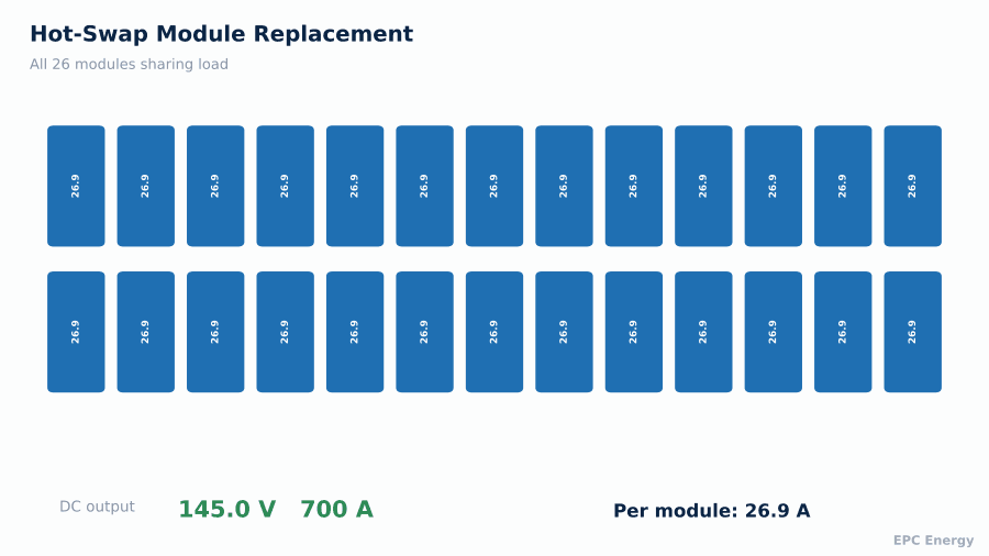
Hot-swap requires a few design features:
- Inrush limiting at module insertion so the bus does not see a step
- Output isolation (OR-ing) so a faulty module cannot draw current from the bus
- Automatic address assignment so the controller recognises a new module
- Mechanical design that makes incorrect insertion impossible
How mean time to repair drives availability: a modular N+1 system with hot-swap maintains far higher availability than a single monolithic unit.

Efficiency at Partial Load: Module Shedding
Most DC systems run well below rated capacity for most of their life. Designs are sized for future growth, redundancy, and peak recharge current. Typical steady-state load might be 30 to 60% of installed capacity.
Shipyards and vessel operators rely on dependable DC power, which is why our work in the Marine & Ship sector is built around those requirements.
Switch-mode modules have an efficiency curve that peaks somewhere around 40 to 70% of their individual rating and falls off at light load. If 26 modules each run at 20%, all of them sit on the steep part of the curve.
Module shedding (sometimes called eco mode or energy optimisation) solves this. The controller switches off modules that are not needed and runs the rest closer to their peak efficiency. Shed modules stay in hot standby and restart within milliseconds if load rises or a running module fails. Running modules are rotated periodically so wear spreads evenly across the shelf.
As load changes, the controller brings modules in and out of service so the active ones operate near their best efficiency point.
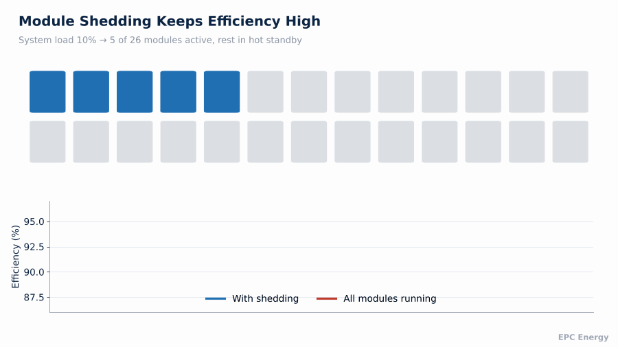
Efficiency of a single switch-mode module against its own load. Module shedding keeps each active module in the high-efficiency band.

Why an Isolation Transformer?
Many modular rectifiers connect directly to the mains, since each module contains its own high-frequency isolation stage. So why did the Greek system include a 125 kVA isolation transformer?
In marine installations, isolation solves several problems at once. It gives full galvanic separation between the ship’s supply and the DC system, which simplifies insulation monitoring and earthing. It attenuates common-mode noise and transients that are common on ship generator networks. And it allows the input voltage to be matched to the module rating, since ship supplies vary from 400 V to 690 V and beyond.
Controller Redundancy: The Often-Forgotten Single Point
A modular power stage removes the single point of failure from the power path. It is easy to reintroduce one in the control path. If all modules depend on one supervisory controller for their voltage reference, a controller failure can disable the whole shelf.
Applications that need very high output current are covered in our article on Custom High Current Rectifiers.
Robust designs avoid this in a few ways. Each module holds its last valid setpoint and keeps running if communication with the controller is lost. Modules default to a safe float voltage on power-up if no controller is present. Current sharing works directly between modules, through an analogue share bus or peer-to-peer communication, so it does not depend on the controller. For the highest availability, a second controller runs in hot standby.
When reviewing a modular rectifier offer, ask specifically what happens on loss of the controller. The answer tells you whether the system is really redundant, or only its power stage is.
Battery Integration
Most modular rectifier systems float a battery on the same DC bus. That adds a few requirements on the module controller. Charge current must be limited as a system total, not per module, otherwise the limit changes every time a module is shed or fails. Temperature compensation of float voltage must be applied to all modules at once. And the battery breaker or fuse must be coordinated with the combined current capability of all modules, plus the battery’s own short-circuit current into a bus fault.
For the Greek marine system, galvanic isolation and redundant architecture were core requirements, so the battery interface was designed together with the module shelf rather than added later.
Where Modular Rectifiers Fit Best
Modular systems are the natural choice for:
- Telecommunications and data centre DC plants
- Marine and offshore DC systems where repair access is limited
- Substations and power plants that need high availability with simple maintenance
- Systems expected to grow, where modules can be added later
Monolithic designs remain better for very high currents, extreme overloads, applications that need thyristor-controlled output such as electrolysis, and some heavy industrial environments where the simplicity of a line-frequency bridge wins.
How EPC Energy Designs Modular Systems
At EPC Energy, we build both monolithic thyristor rectifiers up to thousands of amperes and modular rectifier systems, and we choose between them based on the application rather than on what is in stock. Every system is tested at full load at our Istanbul facility, including hot-swap and failover tests with modules removed under load.
Tell us your voltage, current, redundancy requirement and installation environment, and our engineers will recommend the right architecture.
Frequently Asked Questions
What is a modular rectifier?
A modular rectifier is a DC power system built from multiple identical power modules running in parallel on a common bus. Each module can be replaced individually without shutting the system down.
What does N+1 mean in a rectifier system?
N is the number of modules needed for full load. N+1 adds one extra module so the system carries full load even if any single module fails.
Can rectifier modules be replaced while the system is running?
Yes, in a hot-swap design. Modules have inrush limiting and output isolation so they can be removed and inserted under load.
Are modular rectifiers more efficient?
At partial load, usually yes. Module shedding switches off unneeded modules so the remaining ones run near their peak efficiency.