

6-Pulse vs 12-Pulse Rectifiers and UPS: Harmonics, THD and When 12-Pulse Pays Off

Every three-phase rectifier draws current from the grid in pulses rather than as a clean sine wave. The number of those pulses per mains cycle, six or twelve in most industrial equipment, decides how much harmonic distortion the rectifier pushes back into the supply, how much ripple appears on the DC output, and how large the transformer and generator need to be.
The choice between a 6-pulse and a 12 pulse rectifier is one of the most common line items that separates two quotations for the same industrial rectifier or UPS. The 12-pulse version costs more, weighs more and takes more space. This article explains what you get in return, with the arithmetic behind it, and identifies the applications where 12-pulse is not optional. We refer to two of our own projects: a 28 V DC, 1200 A industrial thyristor rectifier with a 12-pulse dual-bridge architecture, and a 15 kVA 12-pulse industrial UPS for a telecommunications operator in the Middle East.
Our Industrial Rectifier range converts AC supply into controlled DC output for industrial installations.
How a 6-Pulse Rectifier Draws Current?
A three-phase full bridge uses six semiconductors, thyristors or diodes. In each mains cycle, the output voltage is built from six segments of the line-to-line voltages, so the DC output has six ripple peaks per cycle. That is where the name comes from.
With a large DC inductor, the current in each AC line becomes an approximately rectangular block: positive for 120°, zero for 60°, negative for 120°, zero for 60°. A rectangular wave is a sine wave plus a series of harmonics. For this waveform the harmonics that appear are the orders:
h = 6k ± 1 → 5th, 7th, 11th, 13th, 17th, 19th, 23rd, 25th …
Their theoretical magnitudes fall as 1/h. The 5th harmonic is 20% of the fundamental, the 7th is 14.3%, the 11th is 9.1%, the 13th is 7.7%. The total harmonic distortion of current (THDi) of an ideal 6-pulse rectifier is about 30%. Real units with finite inductance often come in between 30% and 40%, and with no DC choke at all it can exceed 80%.
Where uninterrupted power is needed, our Industrial UPS range keeps critical loads running during supply interruptions.
How a 12-Pulse Rectifier Cancels Harmonics?
A 12-pulse rectifier is two 6-pulse bridges fed from two transformer secondaries whose voltages are shifted 30° relative to each other. The classic arrangement is one star (Y) and one delta (Δ) secondary.
Shifting the two bridges by 30° shifts their 5th and 7th harmonic currents by 150° and 210°. Reflected back through the transformer to the primary, these harmonics from the two bridges arrive in opposite phase and cancel. The same happens to the 17th, 19th, 29th and 31st. What remains are the orders:
h = 12k ± 1 → 11th, 13th, 23rd, 25th …
The 5th and 7th, the two largest harmonics, disappear in theory. In practice, small imbalances between the two secondaries leave a residual 5th and 7th of a few percent. Ideal THDi falls to around 15%, and well-built 12-pulse rectifiers typically operate between 8% and 12%.
12-pulse rectifier: a transformer with star and delta secondaries 30° apart feeds two six-pulse bridges. Their 5th and 7th harmonics cancel on the primary side.

Theoretical input current harmonic spectrum. The 12-pulse arrangement eliminates the 5th, 7th, 17th and 19th harmonics.
[Görsel: 6-pulse-vs-12-pulse-harmonic-spectrum.png | alt: Harmonic spectrum bar chart comparing 6-pulse and 12-pulse rectifier input current from 5th to 25th harmonic]
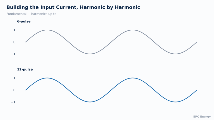
Building the line current harmonic by harmonic: the 6-pulse waveform needs the 5th and 7th to form its blocky shape, while the 12-pulse waveform is already close to a sine wave.
The DC Side: Ripple
The pulse number also sets the frequency and amplitude of the ripple on the DC output.
| Parameter | 6-pulse | 12-pulse |
| Ripple frequency at 50 Hz | 300 Hz | 600 Hz |
| Ripple frequency at 60 Hz | 360 Hz | 720 Hz |
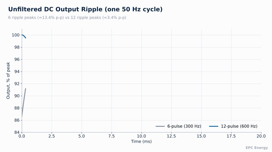
| Unfiltered ripple, peak-to-peak (diode bridge) | ≈13.4% of peak | ≈3.4% of peak |
| Lowest input current harmonics | 5th, 7th | 11th, 13th |
| Typical THDi | 30–40% | 8–12% |
Doubling the ripple frequency and cutting its amplitude by a factor of about four means a much smaller output filter is needed to reach the same ripple specification. For a DC system that must hold ripple below 1% without a battery connected, which is a common specification for loads such as protection relays, this changes the filter design significantly.
Unfiltered DC output: six large ripple peaks per cycle from a 6-pulse bridge against twelve much smaller ones from a 12-pulse bridge.
Why Harmonics Cost Money
Harmonic current is not just a power quality metric. It has physical consequences:
- Transformer heating. Harmonic currents increase eddy current losses. Transformers feeding rectifier loads often need a K-factor rating or derating.
- Cable and neutral heating. Higher RMS current for the same useful power.
- Voltage distortion. Harmonic currents flowing through the source impedance distort the supply voltage, which affects every other load on the same bus.
- Generator sizing. Generators have high source impedance. A 6-pulse rectifier on a generator distorts the voltage heavily and can upset the generator’s voltage regulator. Generators feeding 6-pulse loads are often oversized by a factor of two or more.
- Capacitor resonance. Power factor correction capacitors can resonate with the 5th or 7th harmonic and fail.
- IEEE 519 and local utility rules limit the harmonic current an installation may inject at the point of common coupling.
Our 1200A 12-pulse thyristor rectifier project describes a high-current thyristor rectifier designed and manufactured for an industrial DC supply.
When 12-Pulse Pays Off
12-pulse is not always necessary. For a small rectifier on a stiff grid, a 6-pulse bridge with a good DC choke is usually acceptable. It becomes worth the cost in these situations:
- Generator-backed systems. Any significant rectifier or UPS load running from a standby generator.
- High power. Above roughly 30 to 50 kVA, harmonic current becomes significant relative to the supply transformer.
- Weak grids. Remote sites, islands, ports and industrial zones at the end of long feeders.
- Telecom and sensitive loads on the same bus. Voltage distortion affects other equipment.
- Low ripple without battery. When the DC load must be protected even when the battery is disconnected.
- Utility compliance. When the installation must meet IEEE 519 or similar limits.
For even lower distortion, 18-pulse and 24-pulse arrangements extend the same idea with more transformer phase shifts. Active front ends and active harmonic filters offer an alternative, at higher cost and complexity.
The 15kVA 12-pulse telecom UPS project covers an industrial UPS system designed and manufactured for a telecom site in the Middle East.
Reference Projects
15 kVA 12-Pulse Industrial UPS, Middle East Telecom (2020)
This system was commissioned in 2020 for a telecommunications operator. The 12-pulse input was specified to reduce input harmonics, which in turn reduces voltage distortion for other telecom equipment sharing the supply and limits the oversizing needed for the site’s generator. The UPS includes RS485 communication and a bypass transformer option.
28 V DC, 1200 A 12-Pulse Thyristor Rectifier (2026)
A 33.6 kW industrial rectifier using dual thyristor bridges in a 12-pulse configuration, delivering 1200 A continuously at 28 V DC. At this current, the 12-pulse arrangement reduces both the harmonic load on the input transformer and the filtering needed on the DC side, where large capacitors and inductors at 1200 A are expensive and bulky. Control is DSP-based with Modbus TCP/IP integration. We have also supplied 24 V, 1200 A 12-pulse rectifiers for a thermal power plant in Turkey.
Typical input current THD for different pulse numbers. Each step up requires additional transformer phase shifts.

A Worked Generator Example
Suppose a site has a 100 kVA rectifier load and a standby generator with a subtransient reactance of 15%. A rough rule used by many generator manufacturers is that voltage distortion at the generator terminals should stay below about 5% for stable regulator operation.
With a 6-pulse input, the 5th harmonic alone is around 20% of the fundamental current. Flowing through the generator’s high impedance at five times fundamental frequency, it produces a 5th harmonic voltage of several percent on its own, with the 7th adding more. To keep total distortion in range, the generator would typically be oversized to two or even three times the rectifier rating, so its impedance relative to the load falls.
With a 12-pulse input, the 5th and 7th are mostly gone. The lowest remaining harmonics, the 11th and 13th, are smaller to begin with. The oversizing factor typically drops to around 1.3 to 1.5. On a 100 kVA load, that difference can be the difference between a 150 kVA and a 250 kVA generator, with matching savings in fuel, space and capital cost. The 12-pulse transformer often pays for itself on the generator alone.
Buyers comparing options can review our Industrial Rectifier Price Guide to understand which factors affect cost.
Design Details That Decide Real Performance
Two 12-pulse rectifiers can perform very differently. The details to check:
- Transformer balance. Turns ratios and impedances of the two secondaries must match closely, or residual 5th and 7th harmonics reappear.
- Series vs parallel connection. Bridges in series suit higher voltages. Bridges in parallel need an interphase reactor to share current.
- Firing angle control. In thyristor designs, both bridges must be fired symmetrically.
- Ask for THDi measured at rated load on the factory test, not calculated.
Measuring Harmonics on Site
A factory test proves the design. Site measurements prove the installation. When commissioning a large rectifier or UPS, measure at the point of common coupling with a class A power quality analyser to IEC 61000-4-30, at several load levels. Record THDi, individual harmonics up to at least the 25th, and voltage THD with and without the rectifier running. If the site supply is already distorted by other loads, the difference between the two measurements shows what your equipment actually contributes, which is the figure that matters for IEEE 519 compliance and for any discussion with the utility.
Note also that THDi is a percentage of the fundamental current. At light load, THDi rises even though the harmonic amperes fall. IEEE 519 uses total demand distortion (TDD), referred to maximum demand current, precisely to avoid this misleading effect.
How EPC Energy Builds 12-Pulse Systems
We design and manufacture 6-pulse and 12-pulse thyristor rectifiers, battery chargers and industrial UPS systems, including the phase-shifting transformers, at our facility in Istanbul. Every unit undergoes full-load testing, and on 12-pulse units we measure input harmonics and DC ripple and report them in the test documentation.
Send us your supply conditions, generator size and DC requirements, and our engineers will advise whether 12-pulse is justified.
Frequently Asked Questions
What is the difference between a 6-pulse and 12-pulse rectifier?
A 12-pulse rectifier uses two 6-pulse bridges fed 30° apart through a phase-shifting transformer. This cancels the 5th and 7th harmonics and doubles the DC ripple frequency.
What THD does a 12-pulse rectifier achieve?
Theoretically around 15%. Real units typically measure 8–12% input current THD at rated load, compared with 30–40% for a 6-pulse unit.
Do I need a 12-pulse UPS with a generator?
For significant UPS power on a generator, 12-pulse is strongly recommended. It reduces voltage distortion and the amount of generator oversizing required.
Is 18-pulse better than 12-pulse?
It cancels more harmonics, typically reaching 5–6% THDi, but needs a more complex transformer. 12-pulse is the common industrial balance of cost and performance.