

Custom DC Power Supply for Industrial Applications: Voltage, Current and Design Requirements

Catalogue DC power supplies cover a huge range of needs. If you want 24 V at 10 A for a control panel, there are dozens of good options and you should buy one. But industrial projects regularly fall outside that range: an unusual voltage, a current in the hundreds or thousands of amperes, a load that behaves badly, a requirement for redundancy, a harsh environment, or an interface that no off-the-shelf unit provides.
That’s when a custom DC power supply makes sense. This article explains how to define what you need, which parameters matter most, and how to work with a manufacturer to get a supply that fits your application rather than one that nearly fits.
When does custom make sense?
A custom DC power supply is usually the right choice when one or more of these apply:
- Non-standard voltage or current, such as 145 V DC, 600 A, or a wide adjustment range.
- High power beyond what catalogue modules can deliver without awkward paralleling.
- Specific regulation modes: constant current, constant power, programmable profiles.
- Difficult loads: highly inductive, capacitive, pulsed, regenerative or electrolytic.
- Redundancy with hot-swappable modules and no single point of failure.
- Harsh environment: high temperature, vibration, dust, humidity, marine or military conditions.
- Integration requirements: specific protocols, interlocks, remote control or data logging.
- Certification: class approval, company specifications or sector-specific standards.
If none of these apply, a catalogue product is probably the better choice. Custom design takes engineering time, and you should only pay for it when it adds value.
Understanding the operating envelope

Every DC power supply has an operating envelope: the combinations of voltage and current it can deliver. The chart shows a typical example for a 0–120 V, 0–100 A, 6 kW supply.
Constant voltage (CV). The supply holds the output voltage at the setpoint while the load draws whatever current it needs, up to the limit. Most DC distribution and battery float applications operate here.
Constant power (CP). At higher currents, the supply’s power rating becomes the limit. Voltage falls as current rises, along a hyperbola. In this example, 6 kW means 120 V is available up to 50 A, but at 100 A only 60 V is available.
Constant current (CC). At the current limit, the supply holds current constant and lets the voltage fall. Battery charging, electroplating and many test applications use this mode.
Understanding where your load will operate in this envelope is the first step in specifying a supply. A supply rated “120 V, 100 A” may not deliver both at the same time. If you need 120 V at 100 A, you need a 12 kW supply.
Architecture of a custom DC power supply

The diagram shows a typical architecture for a modern switch-mode industrial DC supply:
- AC input with rectifier and power factor correction (PFC), which keeps the input current close to sinusoidal and the power factor close to unity.
- Isolated DC/DC stage, switching at high frequency through a transformer to provide galvanic isolation and set the output voltage.
- Output filter, reducing ripple and switching noise.
- Output, operating in CV, CC or CP mode.
- Controller, which regulates the output, manages limits and protections, and logs events.
- Remote sense, which measures the voltage at the load rather than at the supply terminals and compensates for cable voltage drop.
- Interfaces: Modbus, Profinet, CAN, analogue setpoints, digital I/O and interlocks.
For high-current, low-voltage applications, line-frequency thyristor designs are also common, especially where robustness and simplicity matter more than size. A manufacturer who builds both can choose based on your requirements.
The parameters you need to specify

The table lists the key parameters with typical industrial values. Here’s what each means and why it matters.
Output voltage
State the nominal voltage and the required adjustment range. If the load needs 48 V nominal but must work between 42 and 56 V, say so. A wide adjustment range affects the design, especially the transformer and the regulation at low voltage.
Output current
Continuous current, peak current and how long the peak lasts. A motor or capacitive load may draw several times its continuous current at start-up. A pulsed load may draw high peaks with low average. These affect semiconductor sizing and cooling very differently.
Regulation
Line regulation is how much the output changes when the input voltage changes. Load regulation is how much it changes from no load to full load. Typical industrial values are ±0.5% and ±1%. Tighter values are possible but cost more.
Ripple and noise
Ripple is the low-frequency AC component on the output (at twice or six times the line frequency, or the switching frequency). Noise is the high-frequency component from switching. Specify both, with the measurement bandwidth, and state whether the measurement is with or without a battery connected.
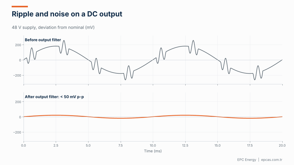
The animation shows a 48 V output before and after the output filter. Before filtering, there’s a few hundred millivolts of low-frequency ripple with bursts of switching noise. After filtering, the output is within 50 mV peak-to-peak. How much filtering you need depends on the load: resistive heaters don’t care, while sensitive measurement electronics may need a few millivolts.
Transient response
When the load changes suddenly, the output voltage dips or overshoots before the control loop corrects it. Specify the load step (for example 10% to 90%), the maximum allowed deviation and the recovery time.
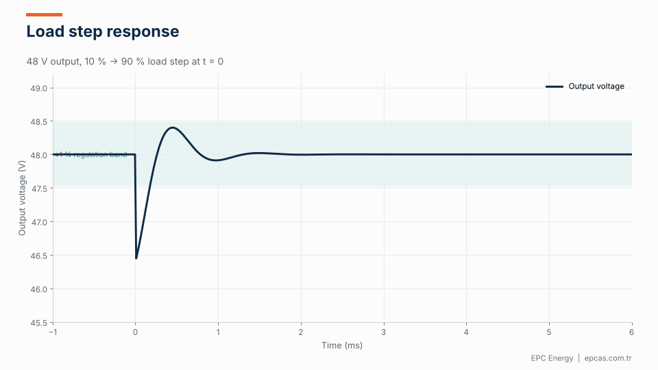
The animation shows a 48 V supply responding to a 10% to 90% load step. The voltage dips by about 1.5 V, overshoots slightly, and settles back inside the ±1% band within about a millisecond. For many industrial loads, a deviation of ±5% recovering within 5 ms is acceptable. Digital electronics and processes sensitive to voltage may need tighter limits.
Isolation
The isolation between input, output and earth, and the test voltage. Reinforced isolation is required where people may contact the output circuit. Industrial supplies are commonly tested at 3–4 kV AC between input and output.
Protections
Overvoltage, overcurrent, short circuit, overtemperature, reverse polarity on the output (important for battery loads), and input under- and overvoltage. Specify whether each protection should latch (require a reset) or recover automatically.
Cables, remote sensing and the voltage at the load
The voltage that matters is the one at the load terminals, not at the power supply. At high currents, cable and busbar resistance can drop a significant voltage. A 10-metre run of 95 mm² copper carrying 200 A, out and back, loses about 0.8 V. That’s more than 1.5% of a 48 V output and over 6% of a 12 V output.
Remote sensing solves this by measuring the voltage at the load through a separate pair of sense wires and adjusting the supply output to compensate. It works well, but it needs care: sense wires should be twisted and routed away from power cables, protected against breakage, and the supply should fall back safely if they’re disconnected. If your load is far from the supply or runs at low voltage and high current, include remote sensing in the specification.
Design requirements: what a good supplier will ask

When you approach a manufacturer for a custom DC power supply, expect them to ask about:
Load behaviour. Resistive, inductive, capacitive or pulsed? Does it regenerate? Inductive loads such as magnets and solenoids can produce voltage spikes when switched off. Capacitive loads draw high inrush. Regenerative loads push energy back into the supply.
Regulation mode. CV, CC, CP or a combination? Do you need programmable profiles, such as a charging curve or a ramped current for a process?
Accuracy. How accurately must the setpoint be achieved and measured? How much drift over temperature and time is acceptable?
Redundancy. Is a single supply acceptable, or do you need N+1 with hot swap?
Interfaces. Which protocol? Analogue setpoint (0–10 V, 4–20 mA)? Interlocks with the process? Data logging?
Mechanical format. 19-inch rack, floor-standing cabinet, wall-mounted, IP-rated enclosure?
Environment. Ambient temperature range, altitude, vibration, humidity, dust.
Compliance. IEC 61204 (low-voltage power supplies), IEC 62368-1 (safety of electronic equipment), EMC standards, and any sector-specific or customer requirements.
Redundancy with N+1 modules
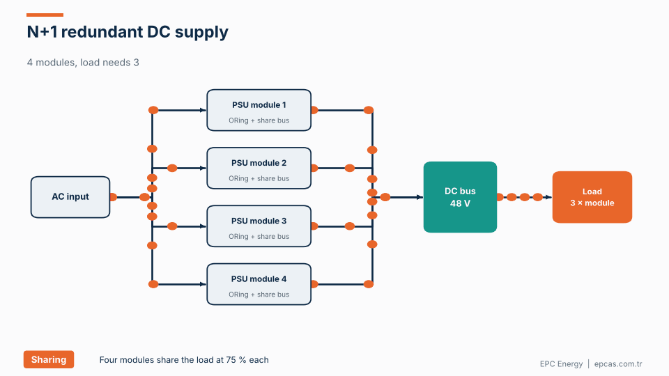
For applications that can’t tolerate downtime, a modular N+1 architecture is the standard approach. The animation shows four modules supplying a load that needs three. Each module connects to the common DC bus through an ORing diode or active ORing MOSFET, and the modules share current through a share bus or digital communication.
In normal operation, each module carries 75% of its rating. If one fails, its ORing device isolates it from the bus, preventing it from pulling the bus down, and the remaining three increase to 100%. The load sees no interruption. The faulty module can then be replaced while the system runs.
Good redundant designs also avoid common-mode failures: separate input breakers per module, independent controllers, and a monitoring system that alarms on any module fault.
Common application examples
Process DC supplies. Electroplating, anodising and electrolysis need high current at low voltage, usually in constant current mode, with ripple and regulation tailored to the process.
DC distribution and battery systems. Telecom (48 V), substations and industrial control (110 or 220 V), and data centres. Usually CV with battery float and current limit.
Test and burn-in systems. Programmable supplies that run profiles, log data and protect the device under test.
Magnet and coil supplies. Inductive loads that require stable current and safe energy dissipation at turn-off.
Marine and defence. Ruggedised supplies with vibration, shock, EMC and environmental qualification.
EPC Energy’s 48 V, 360 kW DC power distribution and backup centre for a telecommunications and data centre client in the Netherlands is an example of how a custom DC system combines high power, modular redundancy and integrated monitoring.
From prototype to production
A custom DC power supply goes through stages that a catalogue product has already completed. Understanding them helps set realistic expectations for schedule and cost.
Design review. The manufacturer converts your specification into a topology, ratings and a bill of materials, and identifies any requirements that conflict or need clarification.
Prototype or first article. For genuinely new designs, a first unit is built and tested in detail, including thermal performance, transient response, ripple and protection behaviour. For designs adapted from existing platforms, this step is often merged with production.
Type tests. Where required, EMC, environmental, vibration or safety tests are carried out, either in-house or at an accredited laboratory.
Factory acceptance test. Each production unit is tested at full load, with ripple, regulation, transient response, protections and communication verified against the specification.
Lifecycle support. Fans and electrolytic capacitors are the usual wear components in DC supplies. Ask for their expected life at your operating temperature, the recommended replacement interval, and how long spare parts will be available.
How to write a good specification
A good specification describes the requirement, not the solution. Instead of “use a 12-pulse thyristor rectifier,” say “input THDi below 12% at full load.” Instead of “use a 6 kW module,” say “deliver 48 V ±1% at up to 120 A continuous.” This gives the manufacturer room to propose the best design.
Include numbers wherever possible. “Low ripple” means nothing; “ripple below 1% rms, 20 MHz bandwidth, without battery” means something.
Include the load data, not just the supply requirement. A manufacturer who understands what the supply is feeding can foresee problems with inrush, regeneration or stability.
Include environmental and installation details from the start. A supply designed for a 25 °C lab won’t survive a 50 °C plant room.
Frequently asked questions
When should I choose a custom DC power supply instead of a catalogue model?
When you need a non-standard voltage or current, high power, specific regulation modes, redundancy, operation in a harsh environment, particular interfaces or sector-specific certification. If a catalogue product meets all your requirements, it’s usually the better value.
What is the difference between CV, CC and CP modes?
In constant voltage (CV) mode, the supply holds the voltage and the load determines the current. In constant current (CC) mode, the supply holds the current and the voltage varies. In constant power (CP) mode, the supply’s power rating limits the output, so voltage falls as current rises.
How do I specify ripple for a DC power supply?
State the maximum value, whether it’s rms or peak-to-peak, the measurement bandwidth, and whether it applies with or without a battery connected. Different loads tolerate very different ripple levels.
What does N+1 redundancy mean for a DC power supply?
The system has one more module than needed to carry the load. If any single module fails, the others carry the full load without interruption. The failed module can usually be replaced while the system is running.
What standards apply to industrial DC power supplies?
Common references include IEC 61204 for low-voltage power supplies, IEC 62368-1 for safety, IEC 60146 for semiconductor converters, and applicable EMC standards, plus any sector-specific or project specifications.
Custom DC power supplies from EPC Energy
EPC Energy has designed and manufactured custom DC power systems since 1977, from compact modules to systems delivering hundreds of kilowatts or more than 1000 A, for telecom, data centres, defence, marine and industrial processes. Read what tailor-made engineering means in practice, then send your voltage, current and load requirements to epcas@epcas.com.tr. Our engineers will respond within two business days.