

AC/DC Auxiliary Power Package for Power Plant EPC Contractors: What to Specify

On a power plant project, the power plant auxiliary power system is a small line in a large budget. It is also one of the systems with the longest list of interfaces: the DCS, protection, turbine controls, switchgear, emergency lube oil pumps, fire and gas, telecom, lighting. When it goes wrong, it rarely goes wrong because a rectifier failed. It goes wrong at the interfaces, in the scope gaps between packages, and in documents that arrive late.
This article is written for engineering, procurement and construction (EPC) contractors and their electrical teams. It covers what the power plant auxiliary power system package should contain, how to size the battery against a real duty cycle, which redundancy architecture suits which plant, and what to demand in testing and documentation. Our reference is a project we delivered in 2023 for a large international EPC venture with Turkish partnership building high-efficiency power plants in Uzbekistan: four complete AC/DC solution sets, each rated 150 kVA, supplied with installation and commissioning.
Every reliable DC system depends on the Industrial Rectifier that sets its voltage and current limits.
What the Package Contains?
A complete power plant AC/DC auxiliary power package typically includes:
- Rectifier / battery charger fed from the plant’s low-voltage AC supply, providing the DC bus and charging the battery
- Battery with racks or cabinets, sized for the duty cycle
- DC distribution panel for DC loads: protection relays, breaker trip and close coils, emergency DC motors, DCS power supplies
- Inverter producing a clean, uninterrupted AC supply from the DC bus
- Static bypass switch transferring critical AC loads to an alternative supply if the inverter is overloaded or faulty
- Bypass transformer or voltage regulator, providing isolation and the correct voltage on the bypass path
- AC distribution panel for uninterrupted AC loads: DCS, SCADA, instrumentation, fire and gas, telecom
- Remote monitoring to the plant DCS over Modbus or IEC 61850
In the Uzbekistan project, each of the four sets included a rectifier with 3 × 400 V, 50 Hz input and 1,600 A DC output, a 230 V AC, 150 kVA inverter, AC and DC distribution panels, a bypass transformer, batteries, battery racks, a remote management system, spare parts, and installation and commissioning services.
Power plant AC/DC auxiliary package: the rectifier feeds the DC bus and battery, the inverter supplies critical AC loads, and the static bypass with bypass transformer provides an alternative path.

Why Buy It as One Package?
Many EPC contractors split this scope: chargers from one supplier, batteries from another, inverters from a third, distribution panels from the switchgear vendor. Each item is cheaper in isolation. The cost appears later, in coordination:
- Who checks that the charger profile matches the battery chemistry chosen by a different supplier?
- Who ensures that DC breaker breaking capacity matches the battery’s short-circuit current?
- Who coordinates selectivity between inverter output, static bypass and AC distribution?
- Who is responsible when the system fails site acceptance and each supplier points to another?
A single-source package puts all of these interfaces inside one engineering team and one factory test. For an EPC contractor, that transfers interface risk to the supplier and shortens commissioning.
Converting stored DC into usable AC is the job of an Industrial Inverter, which is often paired with a rectifier in the same cabinet.
Sizing the Battery: Duty Cycle, Not Average Load
The single most common error in power plant DC system design is sizing the battery for average load times autonomy. Power plant DC loads are anything but constant.
IEEE 485 describes the method used for vented lead-acid batteries in stationary applications, and IEEE 1115 the equivalent for NiCd. The battery is sized against a duty cycle that lists each load, when it starts and how long it lasts:
- Momentary loads in the first minute: breaker tripping and closing operations, motor inrush currents
- Continuous loads for the full duration: protection relays, DCS, inverter input, emergency lighting
- Non-continuous loads for part of the duration: emergency lube oil pump during turbine coast-down, seal oil pump, hydrogen seal systems
- Random loads that may occur at any time, applied at the worst point
- Final loads, often a second set of breaker operations to restore the plant
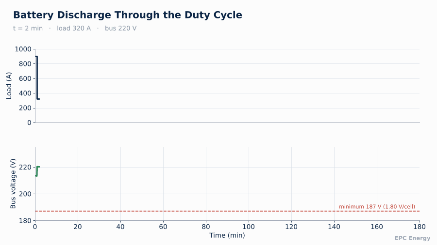
Example DC duty cycle: breaker operations in the first minute, emergency lube oil pump during turbine coast-down, continuous loads throughout, and a final momentary load.

The sizing works period by period, calculating the cell capacity needed for each section of the profile and taking the worst case. Then come correction factors: temperature, design margin and ageing (typically 1.25). Because the first-minute load can be very large, the battery’s high-rate capability matters as much as its ampere-hour rating.
Generating stations depend on continuous auxiliary power, and our work for them is summarised on the Power Plants sector page.
As the duty cycle steps through breaker operations, pump loads and continuous loads, bus voltage falls in proportion. The battery must stay above minimum voltage at the end of the final load.
Sizing the Rectifier
The rectifier must supply the continuous DC load plus the inverter input, and recharge the battery within the required time, typically 8 to 12 hours to 90% capacity after a full discharge. It must also do so with one unit out of service if redundancy is required.
For inverter-fed systems, remember that inverter input current is set by AC load, inverter efficiency and DC voltage. At low battery voltage, the inverter draws more current for the same output. The rectifier and DC distribution must be rated for that worst case.
Four 150kVA units built for a high-efficiency plant in Uzbekistan are documented in the Uzbekistan 150kVA power plant project.
At high current, rectifier topology matters too. For our thermal power plant project in Turkey we supplied 220 V, 700 A and 24 V, 500 A rectifiers, and a 24 V, 1,200 A unit in a 12-pulse configuration to limit input harmonics and output ripple at that current.
Redundancy Architectures
Common configurations, from simplest to most robust:
- Single charger, single battery. Rarely acceptable for main units.
- Two chargers, one battery. Charger redundancy; the battery is still a single point.
- Two chargers, two batteries, bus tie. Each half can supply the full load. Common for main DC systems.
- Fully segregated trains. Two complete, independent AC/DC systems, matching redundant protection and control trains in the plant.
For inverters, parallel redundant operation or a static bypass to a regulated source is standard. The choice should follow the plant’s protection philosophy. If protection is duplicated in “Main 1” and “Main 2” schemes, their DC supplies should be equally independent.
Voltage Window and Cell Count
The DC voltage window must be agreed early, because it fixes the number of battery cells and drives the design of every DC load. A typical 220 V system with lead-acid cells might float at 2.23 V/cell, boost at 2.33 V/cell and end discharge at 1.80 V/cell. With 104 cells, that gives roughly 232 V float, 242 V boost and 187 V end of discharge.
The loads must accept that full window. Protection relays, DC motors, solenoid valves and breaker coils each have their own tolerance, and the narrowest one sets the limit. If the window cannot be satisfied with any cell count, the options are boost charging with loads disconnected, dropper diodes, or a different battery chemistry. Choosing early avoids redesign after the battery has been ordered.
Interfaces EPC Contractors Should Lock Down Early
Most site delays on auxiliary power packages come from a short list of interfaces that are left open during design:
- The DCS signal list and communication protocol, including register maps
- AC input supply arrangements and upstream protection settings
- Cable entry direction and sizes for large DC conductors
- Battery room dimensions, floor loading and ventilation
- Earthing philosophy for the DC system and the inverter output
Settling these at the kick-off meeting saves weeks on site.
The high-capacity rectifier supplied to a thermal station in Turkey is described in Turkey thermal power plant rectifiers.
Blackout Behaviour
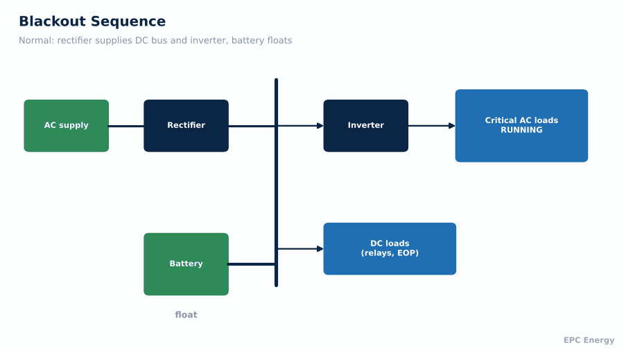
The auxiliary power system earns its cost in a blackout. When the plant loses its AC supply:
- The rectifier output stops, and the battery takes over the DC bus without interruption
- The inverter continues to supply critical AC loads from the DC bus
- Breaker trip operations draw momentary current from the battery
- Emergency DC pumps start and run through turbine coast-down
- When AC returns, the rectifier restarts with a soft-start ramp, recharges the battery under current limit and resumes supplying the loads
Blackout sequence: AC supply is lost, the battery supports the DC bus instantly, the inverter keeps critical AC loads running, and the rectifier recharges the battery when AC returns.
Power Plant Auxiliary Power System: Testing and Documentation
For an EPC contractor, documentation can be as critical as hardware. Owner’s engineers approve drawings before manufacture, and missing documents delay payment milestones.
A complete package should include:
- Single-line diagrams, schematics and general arrangement drawings
- Battery sizing calculation to IEEE 485 or IEEE 1115
- Rectifier and inverter sizing calculations
- Short-circuit and selectivity study for the DC and AC distribution
- Heat load and ventilation data, including battery hydrogen ventilation
- Inspection and test plan (ITP)
- FAT procedure and report
- SAT procedure, commissioning records, operation and maintenance manuals
- Recommended spare parts list for commissioning and two years of operation
The factory acceptance test should be witnessed and should include full-load operation, battery discharge or simulation, static bypass transfers, alarm and communication verification, and a heat run.
Plants that prefer a 220V DC bus for their protection and control circuits will find the details in 220V DC Rectifier for Power Plants.
Typical delivery timeline: engineering and approvals, manufacturing, witnessed FAT, shipment, installation and site acceptance.

Reference Project: Four 150 kVA AC/DC Sets, Uzbekistan (2023)
For a large international venture with Turkish partnership executing engineering, procurement and construction works for high-efficiency power plants in Uzbekistan, we supplied four complete solution sets. Each set included a rectifier with 3 × 400 V, 50 Hz input and 1,600 A DC output, a 230 V AC, 150 kVA inverter, AC and DC distribution panels, a bypass transformer, batteries and racks, a remote management system and spare parts. Our scope also covered installation and commissioning, which kept responsibility for every interface inside one team, from the factory to the energised system on site.
How EPC Energy Works with EPC Contractors
Since 1977, we have designed and manufactured industrial rectifiers, inverters, UPS systems and complete AC/DC packages at our facility in Istanbul, and exported them to more than 55 countries. We work from the contractor’s specification, deliver the calculations and documentation owner’s engineers expect, and test every system at full load before shipment.
Send us your specification and single-line diagram, and our engineers will respond with a technical proposal within two business days.
Frequently Asked Questions
What is included in a power plant AC/DC auxiliary power package?
Rectifiers, batteries, DC distribution, inverters, static bypass, bypass transformer, AC distribution and monitoring, ideally supplied and tested as one system.
How is a power plant battery sized?
Against a duty cycle per IEEE 485 (lead-acid) or IEEE 1115 (NiCd), covering momentary, continuous, non-continuous and random loads, with temperature, margin and ageing factors.
Why should EPC contractors buy the AC/DC system as one package?
A single supplier takes responsibility for every interface between charger, battery, inverter and distribution, which reduces commissioning risk.
What tests should be in the FAT?
Full-load operation, battery discharge or simulation, static bypass transfers, alarm and communication checks, and a heat run.