

110V DC Battery Charger for Substations: Sizing, Specifications and Procurement Guide

Ask a protection engineer what the most important piece of equipment in a substation is and you might expect them to name a transformer or a circuit breaker. Many will tell you it’s the battery. When a fault happens, the relays that detect it and the trip coils that clear it run on DC. If the DC system isn’t there, the breaker stays closed and the fault keeps feeding. The charger is what keeps that battery ready.
The 110 V DC battery charger is not a glamorous product, and that is probably why it’s sometimes specified with less care than it deserves. This guide covers how a substation DC system works, how to size a charger properly, which specification points actually matter, and what to look for when you buy one.
What a 110 V DC system does in a substation

A substation DC auxiliary system has three jobs. It supplies protection relays, bay controllers and communication equipment continuously. It provides the short, heavy current needed to trip and close circuit breakers. And it keeps doing both when the station’s AC auxiliary supply is lost, for as long as the battery is specified to last, typically between two and ten hours depending on the utility.
The usual arrangement is shown above. Two AC auxiliary supplies feed two chargers. The chargers feed a DC switchboard, which also has the battery connected to it. Outgoing feeders go to protection panels, breaker trip and close circuits, RTU and SCADA equipment, emergency lighting and sometimes inverters for essential AC loads.
In normal operation the chargers supply all of the DC load and keep the battery at float voltage. The battery does nothing except wait. When a breaker trips, the battery and chargers share the current spike. When the AC supply fails, the battery takes over instantly, with no switching, because it’s already on the bus.
110 V is the most common nominal voltage for transmission and large distribution substations in Europe, the Middle East and much of Asia. Some utilities use 125 V (common in North America), 220 V (for large stations with long cable runs) or 48 V for communication equipment. The principles below apply to all of them; the numbers change.
Voltage levels: why the cell count comes first

Industrial Frequency Conversion: Connecting 50 Hz, 60 Hz and 400 Hz Systems Efficiently
“110 V” is a nominal figure. In practice the bus voltage moves through a range, and the charger has to manage that range without pushing loads outside their tolerance.
For lead-acid batteries, the standard choice is 54 cells. At a float voltage of around 2.23–2.27 V per cell, the bus sits between about 120 and 123 V. During a boost or equalising charge at 2.33–2.40 V per cell, it rises to roughly 126–130 V. At the end of discharge, typically 1.75–1.80 V per cell, it drops to around 95–97 V.
For NiCd pocket-plate batteries, the cell count is usually somewhere between 84 and 92, depending on the end voltage and boost voltage the system can tolerate. With 86 cells, float at 1.40–1.42 V per cell gives about 120–122 V on the bus, and the end of discharge at 1.10 V per cell gives about 95 V.
Now compare that with the equipment. Most substation devices rated at 110 V DC accept roughly −15% to +10%, or 93.5–121 V. Some protection relays accept a wider band, some narrower. You can see the problem: the boost charge voltage can exceed the upper limit. There are three standard ways to deal with it:
- Disable boost charging where the battery chemistry allows it (common with VRLA, which generally doesn’t need regular equalising).
- Use voltage dropping diodes (sometimes called counter-EMF cells or droppers) between the battery and the load bus, switched in automatically during boost.
- Use separate load and battery chargers, or a dedicated boost charger, so the load bus never sees the boost voltage.
Which one is right depends on the battery, the loads and the utility’s practice. The important thing is that someone has checked. We’ve seen specifications that call for a 2.40 V per cell boost on 54 cells and a +10% load tolerance in the same document. Both can’t be true at once.
The duty cycle: what the battery and charger actually face

Battery sizing for substations normally follows IEEE 485 (for lead-acid) or IEEE 1115 (for NiCd), or the equivalent IEC-based practice. Both start from a duty cycle: a profile of current against time over the required autonomy.
A typical substation duty cycle has three parts:
- The first minute. When AC is lost, it’s often because of a fault. The protection relays operate, several breakers trip simultaneously, communication equipment may spike. This momentary load can be two to three times the continuous load.
- The continuous period. Relays, bay controllers, RTU, indication lamps, emergency lighting. This is the steady load the battery must carry for the specified autonomy (here, eight hours).
- The last minute. Utilities usually require the battery to have enough capacity left at the end to close breakers when supply is restored. Closing coils and spring-charging motors draw heavily.
The chart above shows an example with 62 A for the first minute, 24 A continuously and 48 A in the final minute. The first and last minutes largely decide the battery’s high-rate capacity. The continuous load decides most of its ampere-hours. And the continuous load, together with the battery’s recharge, is what decides the charger.
How to size a 110 V DC battery charger
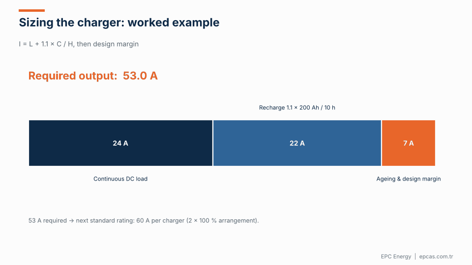
A widely used sizing formula, given in IEEE 946, is:
A = L + (1.1 × C) / H
where A is the charger output current, L is the continuous DC load, C is the ampere-hours removed from the battery during the discharge, H is the recharge time in hours, and 1.1 accounts for charging losses (for lead-acid; NiCd typically uses around 1.2–1.4).
Choosing an Industrial UPS Manufacturer: How to Tell a Builder from an Assembler
Let’s work through the example from the animation:
- Continuous DC load (L): 24 A.
- Battery: 200 Ah VRLA, assumed fully discharged for a conservative design (C = 200 Ah).
- Required recharge time (H): 10 hours.
- Recharge current: 1.1 × 200 / 10 = 22 A.
- Subtotal: 24 + 22 = 46 A.
- Add a design margin for ageing, future load growth and temperature, typically 10–20%: about 7 A.
- Required output: around 53 A.
You would then select the next standard rating above that, here 60 A. In a 2 × 100% redundant arrangement, each charger is rated 60 A and can carry the full load and recharge the battery on its own.
A few things to watch:
- Don’t size on the momentary load. The battery handles the one-minute spikes. If you size the charger to carry a 62 A trip load continuously, you’re paying for capacity that will never be used.
- Check the battery’s maximum charge current. VRLA manufacturers often limit charge current to around 0.2–0.25 C. For a 200 Ah battery, that’s 40–50 A. The charger’s battery current limit must be set accordingly, even if the charger itself is bigger.
- Recharge time is a utility decision. Some require 90% recharge in 8 hours, others 100% in 24. Write it down explicitly.
How the charger charges: IU characteristics and float
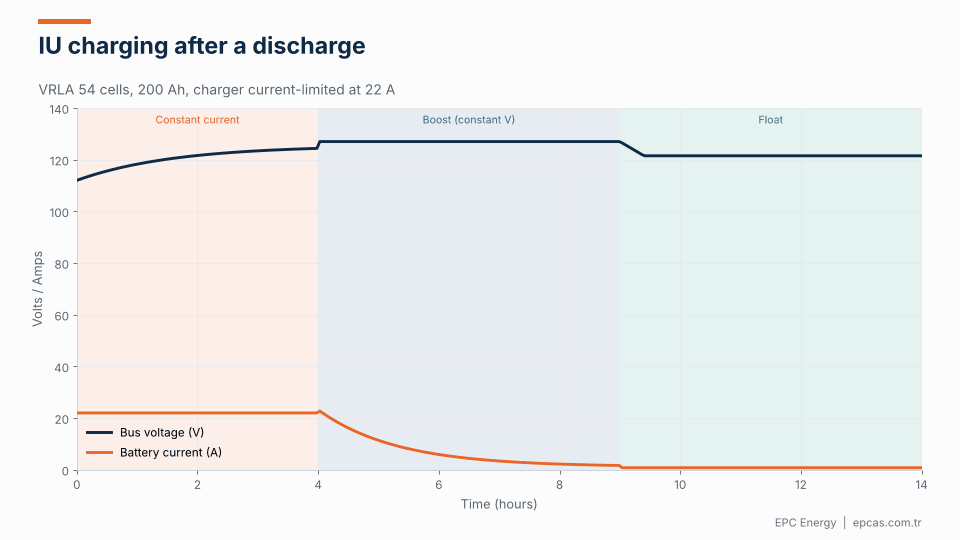
Most substation chargers use an IU (constant current, then constant voltage) characteristic, sometimes called IU0U when a separate float stage follows the boost stage. The animation shows a recharge after a discharge:
- Constant current. The charger delivers its current limit (22 A to the battery, in our example) while the battery voltage rises.
- Constant voltage (boost). Once the voltage reaches the boost setting, the charger holds it there. The current falls naturally as the battery fills.
- After a timer or when the current falls below a threshold, the charger drops back to float voltage, where it stays until the next discharge.
Modern chargers add temperature compensation, lowering the float voltage as the battery gets warmer. For VRLA this is roughly −3 mV per degree per cell. It makes a meaningful difference to battery life in substations without air conditioning, which is most of them in hot climates.
Specification points that separate a good charger from an adequate one

Most chargers on the market will produce 110 V DC. The differences show up in the details, and in how the charger behaves on a bad day.
Ripple with the battery disconnected. A battery acts as a huge capacitor and hides poor filtering. Protection relays and electronics are sensitive to ripple, and the battery will occasionally be disconnected for maintenance. Specify ripple of 1% rms or better *with the battery disconnected*, and ask for it to be tested at FAT.
Voltage regulation. ±0.5% to ±1% static regulation across the full input and load range is a reasonable target. Tighter regulation means more accurate float voltage, which means longer battery life.
Current limiting. Separate limits for total output current and battery charging current, both adjustable.
Input tolerance. Substation AC auxiliary supplies are not always stable. The charger should ride through ±10% voltage and ±5% frequency variations, and tolerate harmonics from other equipment.
Earth fault monitoring. Substation DC systems are usually unearthed (IT). A single earth fault doesn’t cause a trip, but a second one can cause false tripping or failure to trip. An insulation monitoring device, ideally with fault location on outgoing feeders, is essential. Many utilities require it to be part of the charger or DC board.
Short-circuit behaviour. The charger must survive a short circuit on the DC bus and must not prevent downstream DC breakers or fuses from clearing faults. In practice the battery provides most of the fault current, but the charger’s current limit and protection settings need to be coordinated.
Communication. IEC 61850 is increasingly the default for new substations, alongside Modbus and dry contacts for alarms. Agree which data points the SCADA needs early in the project; it saves a lot of back-and-forth.
Environmental rating. Operating temperature, often up to 45–55 °C in non-air-conditioned rooms; altitude; EMC immunity appropriate for a high-voltage environment.
Thyristor or high-frequency switch-mode?
Both technologies are widely used in substations.
Thyristor (SCR) chargers use a line-frequency transformer and a controlled rectifier bridge. They are electrically robust, tolerate surges and harsh supplies very well, are easy to repair with discrete components, and last a long time. They need a substantial output filter to achieve low ripple and are larger and heavier.
High-frequency switch-mode chargers use IGBT or MOSFET stages switching at tens of kilohertz. They’re compact, efficient, offer low ripple with small filters and are often modular, so N+1 redundancy is easy. They have more components and depend more on the quality of design and parts.
Utilities have historically favoured thyristor chargers for transmission substations, and many still do. Switch-mode modular systems are common in distribution and telecom. Our view is that both work well when they’re designed properly and specified correctly. The specification should define performance, not dictate technology, unless the utility has a clear reason.
Redundancy: one charger, two chargers, two batteries
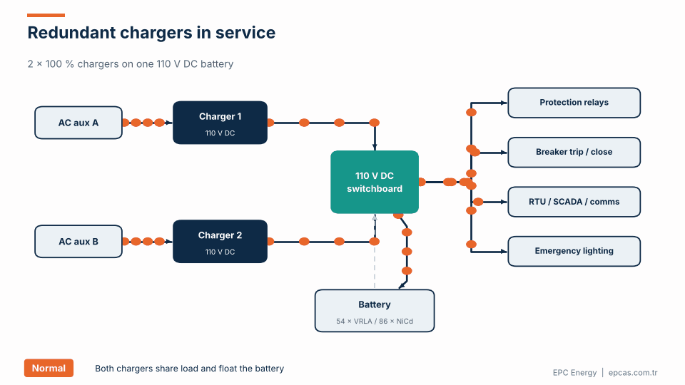
Common arrangements, from simplest to most robust:
- One charger, one battery. Acceptable for small distribution substations. A charger failure leaves the battery as the only source until repair.
- Two chargers (2 × 100%), one battery. The most common arrangement for transmission substations. Either charger can carry the load and recharge the battery. The animation shows what happens when one charger fails: the other picks up the load immediately, and an alarm goes to SCADA. When AC is lost entirely, the battery takes over with no switching.
- Two chargers, two batteries, two DC systems. Used where protection is duplicated into main 1 and main 2 systems, which is standard practice at higher voltages. Each protection system has its own fully independent DC supply.
The choice usually follows the utility’s protection philosophy. If the protection is duplicated, the DC supply should be too.
Procurement tips
Send the battery data. Chemistry, cell count, capacity, manufacturer’s float and boost voltages, maximum charge current. Without this, the charger can’t be configured correctly.
Send the duty cycle and autonomy. Even if the battery has already been sized, the charger supplier should see the numbers.
Specify ripple with the battery disconnected. We’ll keep repeating this.
Ask for the FAT procedure in advance. It should include load tests, current limiting, ripple measurement, transient response, alarm functions, communication tests and a heat run.
Check the supplier’s references. Utilities generally prefer suppliers with installations in comparable substations. Ask for them.
Think about spares and service. A substation charger can run for 20 years or more. Make sure parts will be available.
Frequently asked questions
How do I size a 110 V DC battery charger for a substation?
Use A = L + (1.1 × C) / H: the continuous DC load plus the battery recharge current (ampere-hours to restore, times a charging loss factor, divided by the recharge time). Add a 10–20% design margin and choose the next standard rating. Don’t size the charger on the one-minute tripping load; the battery covers that.
How many cells does a 110 V DC battery have?
Typically 54 cells for lead-acid (VRLA or vented) and between 84 and 92 cells for NiCd, depending on the voltage window the loads can accept.
What ripple is acceptable for a substation battery charger?
A common requirement is 1% rms or less with the battery disconnected. With the battery connected, ripple will be much lower, but the specification should cover the battery-disconnected case because that’s when sensitive loads are most exposed.
Should a substation have two battery chargers?
For transmission substations, yes. Two 100% rated chargers on one battery is the most common arrangement. Where protection is duplicated into two independent systems, two chargers and two batteries are normally used.
Is a thyristor or switch-mode charger better for substations?
Both work. Thyristor chargers are extremely robust and long-lived; switch-mode chargers are compact, efficient and easy to make redundant. The specification should state the required performance and let the supplier propose the topology, unless the utility has a standard.
Talk to EPC Energy about your substation DC system
EPC Energy designs and manufactures industrial rectifiers and battery chargers for power plants, substations and industrial sites, with IEC 61850, Modbus and Profinet integration. Every charger is built and fully tested in our Istanbul facility. Send your battery data and duty cycle to epcas@epcas.com.tr and our engineers will propose a solution sized for your station, not a catalogue model.