

220V DC Rectifier Systems for Power Plants: Technical Requirements and Supplier Selection

There’s a moment in every turbine trip that power plant engineers think about more than they’d like to. The unit is offline, the shaft is still spinning at thousands of rpm, and the main AC supply to the auxiliaries has gone. For the next several minutes, the bearings need oil. The only thing standing between a controlled run-down and a wrecked turbine is a DC motor driving the emergency lube oil pump, fed from the station battery, kept ready by a 220 V DC rectifier.
That’s why the DC system in a power plant is treated as safety equipment, and why the rectifier specification deserves careful attention. This article covers where 220 V DC is used, what the rectifier has to handle, the main technology choices, and how we’d suggest evaluating suppliers.
Why power plants use 220 V DC

Most power plants have at least two DC systems. A lower-voltage system, usually 24 V or 48 V, feeds instrumentation and some control electronics. A higher-voltage system, commonly 110 V or 220 V (125 V or 250 V in North American practice), feeds switchgear control, protection, large DC motors and inverters for essential AC loads.
Higher voltage makes sense when the loads are large and the cable runs are long. A 22 kW emergency oil pump motor at 220 V draws roughly 110–120 A. The same motor at 110 V would need twice that, with heavier cables, bigger breakers and more voltage drop across the turbine hall. For thermal plants, combined-cycle units and large hydro stations, 220 V DC is the common answer.
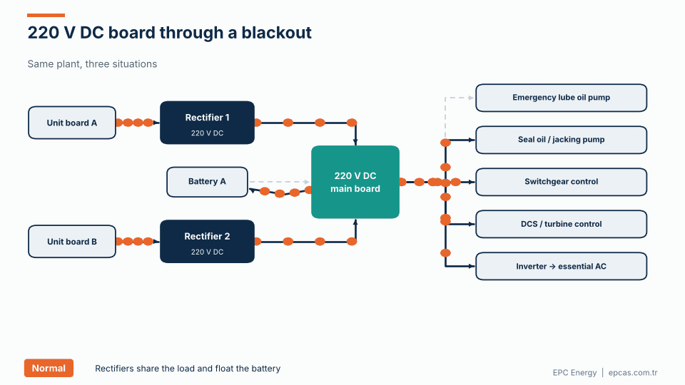
The diagram above shows a typical arrangement. Two unit or station boards feed two rectifiers. Each rectifier feeds a DC main board, with the battery connected directly. Outgoing feeders supply:
- Emergency lube oil pump for the turbine and generator bearings.
- Seal oil pump for hydrogen-cooled generators, and jacking oil pumps that lift the shaft during turning gear operation.
- Switchgear control: breaker trip and close coils, spring charging motors, protection relays.
- DCS and turbine control equipment that must stay alive during transients.
- Inverters that produce essential AC from the DC bus for loads that can’t tolerate interruption.
What the rectifier has to handle

A 220 V DC rectifier in a power plant does three things at once: it supplies the continuous DC load, it keeps the battery at float voltage, and after a discharge it recharges the battery within the required time while still carrying the load.
The load profile is dominated by motors. The chart above shows an illustrative set of running currents for a thermal unit. The emergency lube oil pump is the largest single consumer, followed by the one-minute switchgear tripping load and the seal and jacking oil pumps. Steady loads such as DCS cabinets, emergency lighting and inverters are smaller but run continuously.
Two aspects make power plant DC systems demanding:
Motor starting. DC motors draw a starting current well above their running current, typically two to three times with a resistive or electronic starter, more without. When the emergency oil pump starts, it pulls the bus voltage down. The battery provides most of that current; the rectifier, if it’s still online, contributes up to its current limit. The system has to be designed so that the voltage dip doesn’t drop out contactors or reset control electronics on the same bus.
Long autonomy at high current. Run-down after a trip can take 30 minutes to several hours depending on the turbine. Some plants require the DC system to support a full station blackout for three hours or more. That means large batteries, often 600 to 1500 Ah or more for big units, and rectifiers sized to recharge them.
Voltage levels and the battery
For a 220 V lead-acid system, the battery typically has between 104 and 108 cells. With 104 VRLA cells floating at 2.23 V per cell, the bus sits at about 232 V. At the end of discharge, 1.80 V per cell, it falls to about 187 V.
Equipment is usually rated for 220 V −15% / +10%, giving 187–242 V, although some plants apply a tighter −10% at the load terminals to allow for cable voltage drop. That’s the window the system has to live in.
NiCd systems use roughly 170–180 cells for 220 V, with the exact count chosen so that both the boost voltage and the end-of-discharge voltage fall inside the load tolerance.
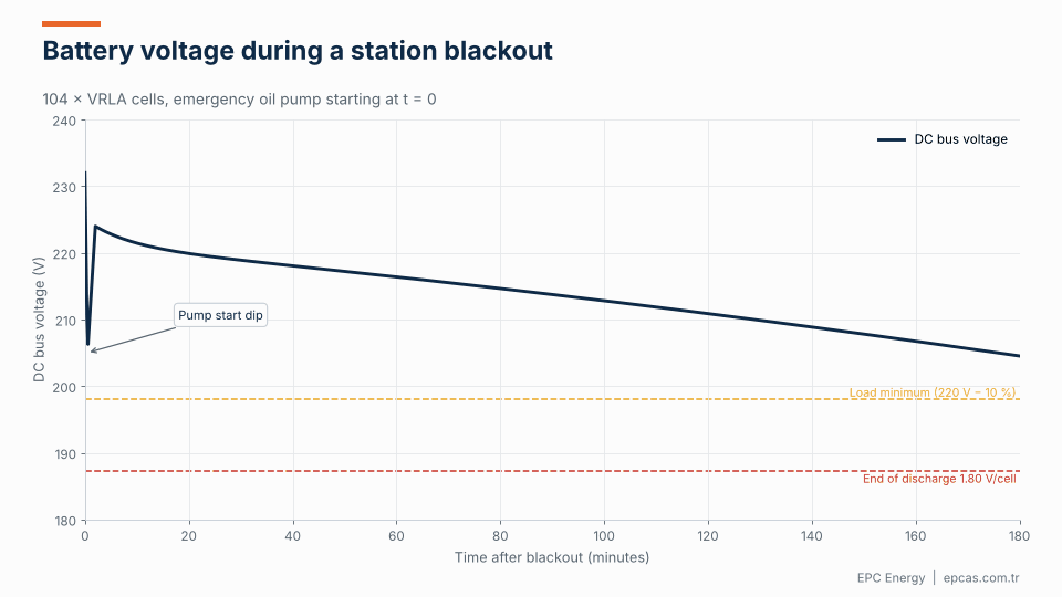
The animation shows the battery voltage during a three-hour blackout for a 104-cell VRLA battery. At the moment the emergency oil pump starts, the voltage dips sharply, then recovers as the motor reaches speed. From there it declines slowly as the battery discharges. A correctly sized battery keeps the bus above the minimum load voltage for the whole duration, with margin to the end-of-discharge limit. An undersized one crosses the load minimum before the run-down is complete, and that’s a situation you don’t want to discover during an actual trip.
Sizing the 220 V DC rectifier
The basic method is the same as for any battery charger:
Rectifier current = continuous load + battery recharge current + margin
The recharge current is usually calculated as (capacity to restore × charging loss factor) ÷ required recharge time. For lead-acid, the factor is around 1.1; for NiCd, 1.2 to 1.4. Recharge times in power plants are often 8 to 12 hours to 90% or 95% of capacity.
So for a plant with 60 A of continuous DC load, a 1000 Ah battery and a 10-hour recharge requirement: 60 + (1.1 × 1000 / 10) = 170 A, plus a 10–15% margin, giving a rectifier of around 200 A.
Things that often get missed:
- Rectifier current limit vs battery charge limit. The rectifier output can be larger than the battery’s maximum permitted charge current, but then a separate battery current limit is needed.
- Boost voltage vs load tolerance. As with substations, boost charging can push the bus above the load limit. Dropping diodes or a separate boost path may be needed.
- Parallel operation. If two rectifiers run in parallel on one bus, they need active load sharing, or one will carry most of the load while the other idles.
- Short-circuit contribution. DC breakers downstream must clear faults reliably. The battery provides most of the fault current, but rectifier current limiting and breaker selectivity should be checked together.
Technology choice: thyristor or IGBT?

Thyristor rectifiers have powered power plant DC systems for decades. A line-frequency transformer steps the voltage down and provides isolation; a phase-controlled thyristor bridge regulates the output; an LC filter smooths it. They are extremely tolerant of surges, short circuits and poor supply quality, and their components are easy to replace. A well-built thyristor rectifier can run for 25 years.
The main drawbacks are input harmonics and output ripple. A 6-pulse bridge draws current with significant 5th and 7th harmonics (input THDi typically around 30%) and produces an output ripple at 300 Hz that needs a large filter. A 12-pulse design uses two bridges fed from phase-shifted transformer secondaries, cancelling the 5th and 7th harmonics (THDi around 10–12%) and doubling the ripple frequency to 600 Hz, which makes filtering easier.
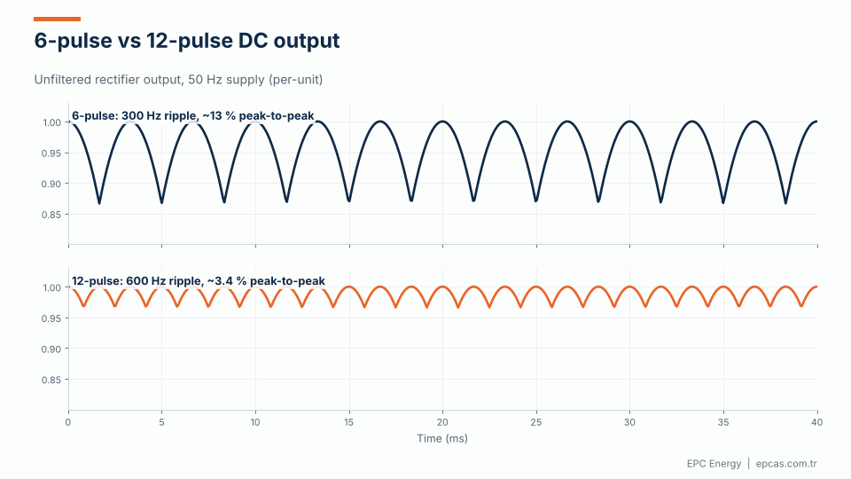
The animation above shows the difference in unfiltered output. The 6-pulse waveform has about 13% peak-to-peak ripple at 300 Hz. The 12-pulse waveform has about 3.4% at 600 Hz. After filtering, both can meet a 1% ripple specification, but the 12-pulse version gets there with a smaller filter and puts much less distortion back into the plant’s auxiliary network.
IGBT high-frequency rectifiers switch at tens of kilohertz. With an active front end, input THDi can be below 5% and power factor close to unity. Output ripple is low with a small filter, the units are compact and they are often modular, which makes N+1 redundancy straightforward.
Which is better? For many power plants, a 12-pulse thyristor rectifier remains the conservative choice: it’s tolerant, predictable and familiar to maintenance teams. For newer plants with strict harmonic limits, limited space, or a preference for modular N+1 designs, IGBT systems make a strong case. We build both, and we’d rather pick the topology after seeing the plant’s specification than before.
Redundancy and system configuration
Common configurations for power plant 220 V DC systems:
- Two rectifiers, one battery, one bus. Each rectifier rated for 100%. One can be taken out for maintenance while the other carries everything.
- Two rectifiers, two batteries, two buses, with a tie. Each bus has its own rectifier and battery. A bus tie allows one rectifier to supply both sides during maintenance. This is very common for large units.
- Three rectifiers, two batteries. A standby rectifier can be switched to either bus.
The animation shows three situations. In normal operation, the rectifiers share the load and float the battery. During maintenance, one rectifier is isolated and the other carries the whole bus. In a station blackout, both AC supplies are lost and the battery feeds the emergency oil pump and other critical loads during the turbine run-down.
The configuration should follow the plant’s single-failure criterion. Ask: if any one component fails, does the turbine still get its emergency oil? If the answer depends on luck, the configuration needs another look.
Earth fault monitoring
Like substation DC systems, power plant DC buses are usually unearthed. A single earth fault doesn’t cause an immediate problem, but it removes a layer of protection, and a second earth fault on the other pole can cause false operation or failure to trip. With large DC networks running through turbine halls and switchyards, earth faults are not rare.
The DC system should include insulation monitoring with alarm to the DCS. For larger systems, an earth fault location system that identifies the faulty feeder saves many hours of searching. Specify it with the rectifier package, so the integration is done once.
Integration with the DCS
Modern plants expect the DC system to report into the DCS: bus voltage, rectifier currents, battery current, battery temperature, alarms, earth fault status and operating mode. Common protocols are IEC 61850, Modbus TCP and Profibus or Profinet, with critical alarms also hardwired.
Agree the signal list early. It’s surprisingly common for the DC system to arrive at site with a perfectly good Modbus map that doesn’t match what the DCS engineers expected.
Supplier selection: eight questions to ask

Power plant rectifiers are long-life equipment. You’ll live with the supplier’s design choices and support for decades. Before the commercial round, we’d ask:
- Is the design your own? Who owns the schematics, the firmware, the control board design? A supplier who designs in-house can support and modify the system for its full life.
- Do you have reference plants? Same voltage, similar current, comparable site conditions. Ask to speak to an operator if possible.
- How does the rectifier behave in a short circuit? Current limit settings, response time, coordination with DC breakers.
- What earth fault detection do you offer? Monitoring only, or feeder-level location?
- How do you integrate with our DCS? Which protocols, which signals, who does the testing?
- What does your FAT include? Full-load test, heat run, current limit, ripple, transient response, communication. Can we witness?
- What’s your spares policy? How long will parts be available? Which components are proprietary?
- What site support can you provide? Commissioning engineers, response times, local partners.
Price matters, of course. But in our experience, the difference between a good and a poor rectifier shows up in year 10, not at commissioning.
Common specification mistakes
A few things we see often in power plant tenders:
- Ripple specified with the battery connected. It tells you nothing about the filter. Specify ripple with the battery disconnected.
- No defined recharge time. “Recharge the battery” isn’t a requirement. “Recharge to 90% in 10 hours while supplying the continuous load” is.
- Ambient temperature copied from the control room spec. DC rooms in turbine buildings can run much hotter. Use the real value.
- Boost voltage and load tolerance not checked against each other. Covered above, but worth repeating.
- Missing motor starting data. The rectifier and battery supplier needs to know the starting current and duration of the emergency oil pump.
Frequently asked questions
Why do power plants use 220 V DC instead of 110 V DC?
Large DC loads, especially emergency lube oil, seal oil and jacking oil pump motors, draw half the current at 220 V compared with 110 V. That means smaller cables, less voltage drop over long runs, and smaller switchgear. Smaller plants and substations often use 110 V.
How many battery cells are used in a 220 V DC system?
Typically 104 to 108 lead-acid cells, or around 170 to 180 NiCd cells, chosen so that float, boost and end-of-discharge voltages stay within the load tolerance.
Is a 12-pulse rectifier necessary for a power plant?
Not always, but it’s common. A 12-pulse thyristor rectifier reduces input harmonics to roughly a third of a 6-pulse design and makes output filtering easier. For large rectifiers or plants with harmonic limits, it’s usually worth it. IGBT rectifiers with active front ends are another option.
How is a 220 V DC rectifier sized?
Continuous DC load plus battery recharge current, plus a design margin. Recharge current is the capacity to restore times a charging factor (about 1.1 for lead-acid), divided by the required recharge time.
What redundancy is typical for power plant DC systems?
At least two 100% rated rectifiers. Many large units use two independent DC buses, each with its own rectifier and battery, connected through a bus tie.
Work with EPC Energy on your power plant DC system
EPC Energy designs and manufactures 220 V DC industrial rectifiers, battery chargers, DC distribution and industrial inverters for thermal, hydro and renewable plants, with DCS and SCADA integration over IEC 61850, Modbus and Profinet. Learn more about our power plant solutions, or read how we approach industrial rectifier manufacturing at the extremes. Send your load list and battery requirements to epcas@epcas.com.tr; our engineers respond within two business days.