

Custom High Current Rectifiers: 500A, 1000A and 1200A DC Power Solutions

Building a 20 A rectifier is straightforward. Building a 1200 A rectifier is a different job. At high current, almost every design decision is dominated by one fact: losses scale with the square of current. A connection that is perfectly adequate at 50 A becomes a hot spot at 1000 A. A semiconductor drop of one volt is trivial at 220 V but costs several percent of efficiency at 28 V. Cooling, busbars and current sharing stop being details and become the core of the design.
This article explains how high current rectifiers in the 500 A to 1200 A range are designed, which applications need them, and what you should specify when you order one. We’ll use a real example: a 28 V DC, 1200 A, 12-pulse thyristor rectifier that EPC Energy designed and built for an industrial client.
Where high DC currents are needed

High current DC is required wherever a process or load needs a lot of power at relatively low voltage. Typical applications include:
- Electroplating and anodising. Plating lines run at a few volts to tens of volts, with currents from hundreds to thousands of amperes per tank.
- Electrolysis, including small and medium hydrogen electrolysers and chlor-alkali processes.
- Aircraft ground power at 28 V DC, where military and civil aircraft need high starting currents and stable supply on the ground.
- Ship DC distribution, for example on vessels with DC bus systems or large battery banks.
- Battery formation and testing, which charges and discharges cells and modules in production.
- Cathodic protection for pipelines and marine structures, usually at lower currents but very long duty cycles.
- Telecom and data centre DC plants, often at 48 V with total currents in the thousands, built from paralleled modules.
The chart gives indicative current ranges per rectifier. Most custom projects we see fall between 500 A and 2000 A.
Project: 3 × 380 Vac / 28 Vdc – 1200 A Industrial Thyristor Rectifier
What changes between 500 A, 1000 A and 1200 A

The table summarises how the design typically changes as the current rises.
At around 500 A, many designs are still possible. A 6-pulse thyristor rectifier with forced-air cooling works well, as do modular IGBT systems with several paralleled modules. Output conductors may still be cables, although busbars become attractive.
At around 1000 A, 12-pulse thyristor designs become common, because they reduce input harmonics and make output filtering more manageable. Modular N+1 systems are another strong option. Copper busbars are standard, and cooling usually needs ducted forced air.
At 1200 A and above, especially at low voltages like 12–48 V, losses in semiconductors, magnetics and conductors dominate. 12-pulse thyristor rectifiers with careful busbar design are a common solution. Water cooling becomes worth considering, particularly for enclosed or hot environments. Laminated busbars help reduce inductance and improve current distribution.
These are patterns, not rules. The right design depends on voltage, ripple requirement, duty cycle, site conditions and whether redundancy is needed.
A real example: 28 V DC, 1200 A, 12-pulse thyristor rectifier

One of our recent projects was a 3 × 380 V AC to 28 V DC, 1200 A industrial rectifier, rated at 33.6 kW continuous output. The diagram above shows the architecture.
Input transformer with two secondary windings, one delta and one star, giving two three-phase systems shifted by 30 degrees.
Two thyristor bridges, one on each secondary. Each bridge is phase-controlled to regulate the output.
Interphase reactor, which allows the two bridges to operate in parallel and share current while their output ripples are offset.
LC output filter, sized to meet the ripple requirement.
DC busbar output rated for continuous 1200 A.
DSP-based control with Modbus TCP/IP integration for monitoring and remote setpoints.
Why 12-pulse? At this power level, a 6-pulse rectifier would draw significant 5th and 7th harmonics from the supply and produce ripple that needs a much larger filter. The 12-pulse arrangement cancels those harmonics at the input and doubles the ripple frequency at the output.
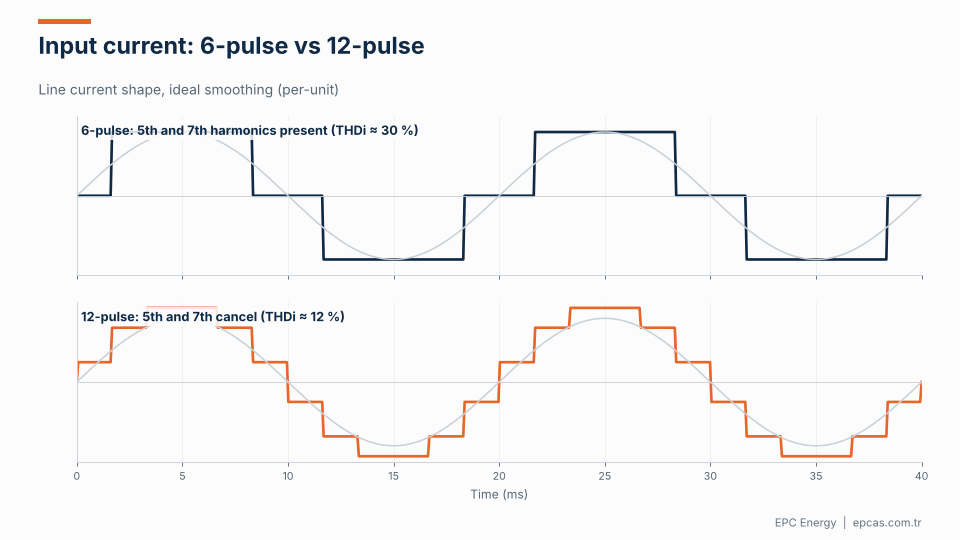
pulse rectifiers showing reduced harmonics
The animation compares the line current drawn by 6-pulse and 12-pulse rectifiers, with a reference sine wave in grey. The 6-pulse current is a quasi-square wave with total harmonic distortion around 30%. The 12-pulse current is stepped and much closer to a sine, with THDi around 12%. For a 33.6 kW load that’s a meaningful reduction in heating and voltage distortion on the plant network.
Losses and heat: the real design constraint
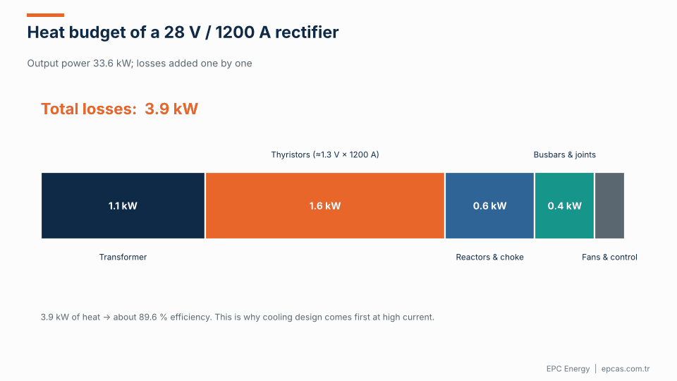
The animation builds up the heat budget for a 28 V, 1200 A rectifier:
- Transformer: around 1.1 kW in copper and core losses.
- Thyristors: around 1.6 kW. With roughly 1.3 V forward drop at 1200 A, conduction losses alone are about 1.56 kW.
- Interphase reactor and filter choke: around 0.6 kW.
- Busbars and joints: around 0.4 kW. At 1200 A, a few tens of micro-ohms per joint adds up.
- Fans and control: around 0.2 kW.
That’s about 3.9 kW of heat for 33.6 kW of output, or roughly 89.6% efficiency. This isn’t a sign of a poor design. It’s physics: at 28 V, a 1.3 V semiconductor drop is almost 5% of the output voltage by itself. At 220 V the same drop would be under 0.6%.
The practical consequences:
- Cooling must be designed first, not added at the end. Heat sinks, airflow paths, fan redundancy and, at higher power, water cooling.
- Every joint matters. Busbar joints need correct surface preparation, bolt torque and contact area. A poorly made joint can run 30–40 °C hotter than its neighbours and degrade over time.
- Thermal testing at FAT is essential. A heat run at full current, with thermal imaging of busbars and joints, catches problems before they reach site.
Thyristor or IGBT at high current?

Thyristor rectifiers are robust, simple and very tolerant of overload and fault conditions. They handle high currents with relatively few, large devices. Their weakness is input harmonics (mitigated by 12- or 18-pulse designs), lower power factor at reduced output voltage, and larger filters.
IGBT-based rectifiers, usually built from paralleled modules, switch at high frequency. They achieve good power factor and low harmonics with an active front end, need smaller filters, respond quickly to load changes and suit modular N+1 redundancy. At low output voltages they can use synchronous rectification to reduce conduction losses.
The chart shows typical efficiency curves for 1000 A class rectifiers at 48 V. IGBT modular designs tend to hold slightly higher efficiency across the load range, and do better at partial load. Thyristor designs remain very competitive at full load and are hard to beat on robustness and simplicity.
For processes such as electroplating, where the rectifier runs continuously at high load and must survive short circuits in the tank, thyristor designs are common. For applications that need tight regulation, fast response, high power factor or redundancy, modular IGBT systems are often the better fit.
Modular N+1 systems
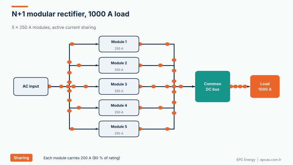
For high-current applications that can’t tolerate downtime, a modular design with N+1 redundancy is a strong option. The animation shows five 250 A modules supplying a 1000 A load:
- Normal operation. All five modules share the load equally, each at 200 A (80% of rating).
- Module fault. One module trips. The remaining four increase to 250 A each and the load sees no interruption.
- Hot swap. The faulty module is replaced while the system is running, and sharing rebalances automatically.
Active current sharing is essential. Without it, small differences in output voltage between modules cause unequal loading, and the busiest module ages fastest. Good designs use a dedicated share bus or digital communication between modules.
EPC’s 145 V DC, 700 A modular rectifier system for a marine customer in Greece is an example of this approach: redundant modules, isolation transformer and a common DC bus, sized so that the vessel’s DC loads never depend on a single power stage.
Busbars, terminals and mechanical design
At 1000 A and above, mechanical design is electrical design.
- Busbar sizing is based on temperature rise, not just current density. Ambient temperature, enclosure ventilation and busbar orientation all matter.
- Laminated busbars reduce loop inductance, which helps with switching transients in IGBT designs and improves current sharing.
- Terminal design must suit the customer’s cables or busbars. Specify the connection method early: number and size of cables, lug type, busbar dimensions.
- Short-circuit forces between busbars can be large. Supports must withstand them.
- Maintenance access should allow torque checks and thermal inspection without dismantling half the cabinet.
Ripple and regulation at high current
Ripple specifications vary widely by application. Electroplating processes often accept a few percent, although some decorative and precision plating processes need less. Battery charging and DC distribution typically need 1% or better. Electrolysis processes may be sensitive to ripple because it affects efficiency.
State the ripple requirement as a percentage of output voltage, specify whether it’s rms or peak-to-peak, and say whether it applies with a battery connected. Also specify regulation (constant voltage, constant current or both) and the required accuracy. High current processes frequently run in constant current mode with a voltage limit.
Overload and short-circuit behaviour
High current processes are not gentle loads. In electroplating, a part touching both the anode and cathode bar creates a dead short in the tank. In battery testing, a fault in the device under test can do the same. In DC distribution, a downstream breaker must be able to clear a fault without the rectifier giving up first.
A good high current rectifier needs a clear strategy for each case:
- Fast electronic current limit, which holds the output current at a safe value within milliseconds of a short, protecting both the rectifier and the process.
- Defined overload capability, for example 110% for 60 seconds or 150% for 10 seconds, so that legitimate peaks don’t cause nuisance trips.
- Coordinated DC protection, with the rectifier’s current limit and downstream DC breakers or fuses chosen together, so the faulty branch clears before the rectifier shuts down the whole bus.
- Safe energy discharge for inductive loads such as magnets or long busbar runs, so that switching off doesn’t produce damaging voltage spikes.
These behaviours should be tested at FAT, not just described in the manual.
Installation tips
Large rectifiers are often installed by the customer’s own contractor. A few points save trouble at commissioning: keep the output busbar or cable run as short as possible to limit both voltage drop and losses; respect the manufacturer’s clearances for airflow; torque every site-made connection and check it with a thermal camera after the first hours at full load; and make sure the plant’s AC feeder and protection are sized for the rectifier’s input current, including its power factor at your operating point.
What to specify for a high current rectifier
When you request a quote for a high current rectifier, include:
- Output voltage (nominal and adjustment range) and output current (continuous and peak, with duration).
- Regulation mode: constant voltage, constant current, or both, with accuracy.
- Ripple limit, with measurement conditions.
- Load type: resistive, electrolytic, battery, motor, inductive.
- Duty cycle: continuous, intermittent, with overload requirements.
- AC input: voltage, phases, frequency, tolerances, harmonic limits.
- Cooling: air or water; water quality and temperature if water.
- Ambient conditions: temperature range, humidity, altitude, IP rating.
- Output connections: busbar or cables, size and location.
- Control and communication: local HMI, remote setpoints, protocols.
- Redundancy: single unit, N+1, 2 × 100%.
- Standards: IEC 60146, IEC 61439 for assemblies, and any project-specific requirements.
Frequently asked questions
What is a high current rectifier?
A rectifier that converts AC to DC at high output currents, typically from several hundred to several thousand amperes. They’re used in electroplating, electrolysis, aircraft ground power, ship DC systems, battery testing and large DC distribution.
Should a 1000 A rectifier be 6-pulse or 12-pulse?
At this power level, 12-pulse is usually preferred because it significantly reduces input harmonics and makes output filtering easier. A 6-pulse design can be acceptable for smaller ratings or where harmonics aren’t a concern. IGBT designs with active front ends are another option.
Why is efficiency lower for low-voltage, high-current rectifiers?
Semiconductor forward drops and conductor losses are roughly fixed in volts or proportional to current squared, not to output voltage. At 28 V output, a 1.3 V semiconductor drop is almost 5% of output; at 220 V, it’s under 1%.
How are high current rectifiers cooled?
Usually by forced air with dimensioned heat sinks and ducted airflow. At higher power densities, in enclosed spaces or in hot environments, water cooling is used. Cooling design should be part of the initial specification.
Can high current rectifiers be made redundant?
Yes. Modular designs with N+1 redundancy use several paralleled modules with active current sharing. If one fails, the others take over its share without interrupting the load. Faulty modules can often be hot-swapped.
High current DC from a manufacturer that has built it
EPC Energy designs and manufactures custom industrial rectifiers for high current applications, including the 28 V DC, 1200 A 12-pulse thyristor rectifier described here. We’ve written more about why real rectifier capability is proven at the extremes. If you need 500 A, 1000 A, 1200 A or more, send your requirements to epcas@epcas.com.tr and our engineers will propose a design.