

400Hz Frequency Converter for Aviation and Defense: Specifications and RFQ Guide

Aircraft electrical systems run at 400 Hz for a simple reason: weight. Transformers and motors get smaller as frequency rises, and on an aircraft every kilogram counts. Military ships, radar systems, missile systems and many avionics test benches adopted the same frequency for the same reason, or because they need to power equipment designed for aircraft.
On the ground, though, the grid runs at 50 or 60 Hz. Bridging the two is the job of the 400 Hz frequency converter. This guide explains how modern converters work, which standards apply, the engineering issues that make 400 Hz different, and what to include in an RFQ.
Where 400 Hz power is needed
- Aircraft ground power. Parked aircraft use ground power units (GPUs) to run avionics, lighting and air conditioning without burning fuel in the auxiliary power unit. Large airports and military air bases use fixed 400 Hz systems at stands and hangars.
- Military ships. Many naval vessels have 400 Hz distribution for weapons, radar, navigation and communication systems.
- Radar and air defence systems, both fixed and mobile.
- Avionics test and repair workshops, where aircraft equipment is tested on the bench.
- Simulators and training systems that use real aircraft equipment.
- Some industrial applications, such as high-speed spindles and specific test equipment.
The standard output is 115 V phase-to-neutral, 200 V phase-to-phase, three-phase, four-wire at 400 Hz. Ratings typically range from a few kVA for test benches to 90 kVA or more for aircraft ground power, with larger systems for central airport installations.
How a solid-state 400 Hz converter works

Older 400 Hz systems used rotating motor-generator sets. Modern installations almost always use solid-state converters, which are more efficient, quieter, need less maintenance and give better voltage and frequency control.
The diagram shows a typical topology:
- Input rectifier converts 50 or 60 Hz AC to DC. It may be a 6-pulse, 12-pulse or active front end, depending on harmonic requirements. An input filter reduces conducted emissions.
- DC link stores energy in capacitors and decouples input from output. An optional battery can be connected here for ride-through.
- IGBT inverter generates a PWM output at 400 Hz.
- Output transformer and sine filter produce a clean sinusoidal 115/200 V output and provide galvanic isolation. The output transformer also gives a properly referenced neutral for four-wire loads.
- Output distribution feeds the aircraft, radar or test benches.
The controller regulates output voltage and frequency, often with fast per-phase regulation to handle unbalanced loads.
50 Hz vs 400 Hz: why it’s not just a different number
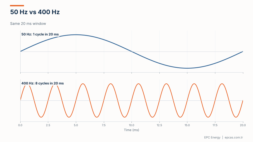
In the time a 50 Hz supply completes one cycle (20 ms), a 400 Hz supply completes eight. That has practical consequences beyond weight savings.
Cable voltage drop

Cable resistance doesn’t change with frequency (ignoring skin effect), but reactance does, in direct proportion. At 400 Hz, a cable’s inductive reactance is eight times what it is at 50 Hz. For larger cables, where reactance is already comparable to resistance, this dominates the voltage drop.
The chart shows a calculated example: a 90 kVA load at 200 V, power factor 0.8, on 95 mm² copper cable. At 30 metres, the voltage drop is about 1.4% at 50 Hz and about 3.6% at 400 Hz. At 60 metres, the 400 Hz drop exceeds 7%.
Three practical consequences:
- Locate converters close to the load. Airport systems often use point-of-use converters at each stand rather than a central converter with long 400 Hz cables.
- Use low-reactance cable designs. Special 400 Hz cables with multiple conductors arranged to reduce inductance.
- Use line drop compensation. Many converters can measure output current and raise their voltage to compensate for cable drop, so the voltage at the aircraft is correct.
Unbalanced loads
Aircraft and avionics often draw unequal current on the three phases. Single-phase test benches can be extremely unbalanced. A good 400 Hz converter must maintain balanced phase voltages under significant load unbalance, which requires per-phase control and an output transformer designed for it.
No mains bypass
A conventional UPS can transfer the load to the mains if the inverter fails. A 400 Hz converter can’t: there is no 400 Hz mains to fall back on. If continuity matters, it has to be designed in, either with redundant converters, a battery on the DC link, or both.
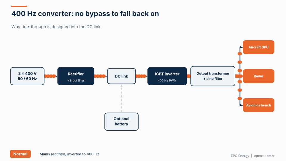
The animation shows normal operation, input loss with an optional DC-link battery maintaining output, and the critical case: an inverter fault with no bypass path. For radar and defence systems, that last case is why N+1 or 2N redundant converter configurations are common.
Standards that define 400 Hz power quality

MIL-STD-704 defines the characteristics of aircraft electrical power, including steady-state voltage and frequency limits, transients and distortion. Equipment designed for military aircraft is qualified against it, so ground power and test equipment that feeds it usually has to comply. Make sure to identify the revision; requirements changed between revisions.
MIL-STD-1399, Section 300 defines the AC electrical power interface on US Navy ships and is widely referenced by other navies. It describes Type I (60 Hz), Type II and Type III (400 Hz) power with different tolerances. Type III is the more tightly regulated 400 Hz supply.
ISO 6858 covers aircraft ground support electrical supplies and is commonly used for civil ground power.
SAE ARP5015 covers ground equipment 400 Hz power, often referenced by airports.
Project or platform specifications for radar, weapons systems and simulators often add their own requirements for harmonics, transients and EMI.
Ask the end user which standard the connected equipment is qualified to. That defines the converter’s output requirements.
Output quality: what to specify
Typical output requirements for a 400 Hz converter, depending on the standard:
- Voltage regulation: often ±1% to ±2% steady state, phase-to-neutral.
- Frequency stability: often ±0.1% to ±0.5% for solid-state converters.
- Total harmonic distortion: typically below 3–5% with linear load.
- Phase balance: phase angle and voltage balance under specified unbalanced load.
- Transient response: maximum deviation and recovery time for a step load.
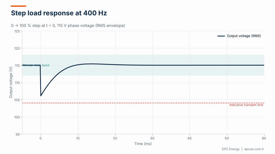
The animation shows the output voltage after a 0 to 100% step load. The voltage dips, then recovers into the steady-state band within a few milliseconds. The limits come from the applicable standard; MIL-STD-704 and MIL-STD-1399 both define transient envelopes that equipment must respect. A converter with weak transient response may pass steady-state tests and still cause trips in sensitive avionics during load changes.
Load power factor and type
Aircraft and radar loads rarely look like a simple resistor. Ground power for aircraft typically runs at a power factor between 0.8 and 0.9 lagging, because of motors, transformers and lighting ballasts. Radar transmitters can draw sharp, pulsed currents synchronised with their transmit cycle. Avionics test benches are dominated by switch-mode power supplies with non-linear current waveforms.
Each of these stresses the converter differently. Low power factor increases the current for the same kW, so the converter’s kVA rating and its output transformer must account for it. Pulsed loads demand fast voltage regulation and enough DC-link energy to prevent visible voltage modulation. Non-linear loads require an output stage and filter that keep voltage distortion within limits despite distorted current. Describe the load as precisely as you can in the RFQ; it’s the most useful single piece of information for sizing the converter correctly.
Overload and inrush
Aircraft and radar loads include motors, transformers and power supplies with high inrush currents. Ground power units also see high currents when aircraft systems start. The converter must handle short-term overloads without collapsing voltage. Typical requirements are 125% for 10 minutes and 150% for 30 to 60 seconds, but the actual requirement depends on the load. Specify it based on the connected equipment, not on a generic figure.
Environment
400 Hz converters are installed in very different places:
- Airport stands and hangars: outdoor or semi-outdoor, exposed to weather, jet blast, de-icing fluids. Robust enclosures and corrosion protection.
- Military shelters and mobile systems: vibration, shock, wide temperature ranges, often MIL-STD-810 environmental testing.
- Naval vessels: shipboard requirements for vibration, inclination and humidity, plus military EMI requirements.
- Workshops and laboratories: benign environments but often strict EMI requirements.
EMI is particularly important around avionics and radar. MIL-STD-461 is the common reference for military equipment; civil installations use IEC or EN EMC standards.
Solid-state vs rotary
Rotary motor-generator sets are still found in older installations and some naval systems. They provide very clean output, inherent isolation and good tolerance to short-term overload. But they’re less efficient (often 80–88%), noisy, heavy and need regular maintenance of bearings and brushes.
Solid-state converters reach 90–95% efficiency, are quieter and lighter, and have fewer moving parts. With proper output filtering and transformer design, their waveform quality matches or exceeds rotary sets. For new installations, solid-state is almost always the right choice.
Point-of-use or central system?
Airports and air bases have two main ways to deliver 400 Hz power to aircraft.
Central systems use one or more large converters in a plant room, distributing 400 Hz through long cables to each stand. They concentrate maintenance in one place, but the cable reactance problem described above becomes severe. Some central systems distribute at a higher voltage and step down at each stand to reduce losses.
Point-of-use systems put a converter at each stand or gate, often mounted under the passenger boarding bridge or in a pit. The 400 Hz cable to the aircraft is short, so voltage drop is easy to manage. Each converter only runs when an aircraft is connected. Most modern airport installations follow this approach.
For military hangars, test cells and shipboard systems, the decision depends on the layout and the number of consumers, but the same principle applies: keep 400 Hz cables short wherever possible.
Testing a 400 Hz converter
A factory acceptance test for a 400 Hz converter should go beyond a simple load run. A thorough FAT includes:
- Steady-state voltage and frequency at no load, partial load and full load, on each phase.
- Waveform distortion with linear and, if relevant, non-linear loads.
- Unbalanced load tests, checking phase voltage balance and phase angle.
- Step load tests, recording voltage transients against the applicable standard’s envelope.
- Overload and short-circuit behaviour, confirming current limiting and recovery.
- Line drop compensation, if specified, at the design cable length.
- Heat run at rated load until temperatures stabilise.
- Alarm and communication checks.
Ask for recorded waveforms, not just pass/fail ticks. They show how the converter really behaves.
400 Hz converter RFQ checklist

To get an accurate quote for a 400 Hz frequency converter, include:
- Output: voltage (115/200 V standard), phases, kVA rating, expected load power factor.
- Applicable standard: MIL-STD-704 (with revision), MIL-STD-1399-300 (with type), ISO 6858, or project specification.
- Load type: linear, rectifier-based electronics, motors, pulsed radar loads.
- Unbalance: maximum expected single-phase or unbalanced loading.
- Transients: step load requirements, maximum deviation and recovery times.
- Overload: magnitude and duration.
- Cable run: length and size to the load, need for line drop compensation.
- Input supply: voltage, frequency, harmonic limits, generator or grid.
- Ride-through and redundancy: battery on DC link, N+1, 2N.
- Environment: indoor, outdoor, shelter, shipboard; temperature range; MIL-STD-810 if applicable.
- EMI: MIL-STD-461 or civil EMC requirements.
- Monitoring and control: local display, remote monitoring, protocols.
Frequently asked questions
Why do aircraft use 400 Hz power?
Higher frequency allows smaller and lighter transformers and motors. On aircraft, weight savings matter more than the disadvantages of 400 Hz, such as higher cable reactance.
What is the difference between a 400 Hz frequency converter and a UPS?
A UPS outputs the same frequency as its input (usually) and can transfer to mains bypass if it fails. A 400 Hz converter changes the frequency, so there is no mains bypass; ride-through and redundancy have to be designed in.
What standard applies to 400 Hz ground power?
For military aircraft, MIL-STD-704. For naval systems, MIL-STD-1399 Section 300. For civil aircraft ground power, ISO 6858 and SAE ARP5015. Project specifications may add requirements.
Why is cable length important for 400 Hz systems?
Cable reactance is eight times higher at 400 Hz than at 50 Hz, so voltage drop is much larger for the same cable. Converters should be placed close to the load, low-reactance cables used, or line drop compensation applied.
Solid-state or rotary 400 Hz converter?
Solid-state converters are more efficient, quieter, lighter and need less maintenance. With proper filtering they provide excellent waveform quality. Rotary sets remain in some legacy installations.
400 Hz converters from EPC Energy
EPC Energy designs and builds solid-state frequency converters for aviation, defence and naval applications, with MIL-STD compliant, vibration and EMI resistant designs for land, air and naval platforms. Read why frequency converters are almost never a stock item, then send your requirements to epcas@epcas.com.tr. Our engineers will review your standard, load profile and installation and propose a tailored design.