

Industrial UPS for DCS and PLC Systems: Sizing, Redundancy and Battery Autonomy

A distributed control system can be designed with redundant controllers, redundant networks and redundant I/O, and still go down because of one breaker in the wrong place. We’ve seen it happen. The power supply to a control system is often treated as an electrical detail that the electrical team handles while the automation team focuses on the “real” system. In practice, the UPS and its distribution are part of the control system’s availability, and they deserve the same attention.
This article covers how to size an industrial UPS for DCS and PLC loads, how to choose a redundancy architecture, how to think about battery autonomy, and the often-overlooked question of fault clearing in UPS-fed distribution.
What a DCS or PLC needs from its power supply
Control systems are electronic loads. They draw power through switch-mode power supplies, are sensitive to voltage interruptions longer than a few milliseconds, and generally expect a clean sinusoidal AC supply at 230 V or 110 V, or a DC supply at 24 V.
Modern DCS and safety system cabinets usually have dual redundant power supplies, each fed from a separate source. That’s a design feature you can use: if the UPS architecture provides two independent feeds, a single upstream failure doesn’t stop the controllers.
The UPS has four jobs:
- Isolate the control system from the plant network, which may have harmonics, dips and transients from motors and drives.
- Keep the system running through short interruptions, such as transfers between incomers or generator start.
- Provide enough autonomy for an orderly shutdown or until a standby source takes over.
- Not become a single point of failure
Typical architecture: 1+1 parallel redundant

The most common architecture for DCS power is two industrial UPS units in parallel redundant (1+1) configuration, as shown above. Each UPS is rated for the full load. In normal operation they share it, each carrying about 50%. Their outputs connect to a common bus, which feeds an AC distribution board with selective miniature circuit breakers (MCBs) or fuses for each cabinet.
The two UPS units are fed from separate supplies where possible, so that a failure upstream affects only one.
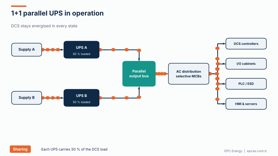
The animation shows the three states:
- Both UPS units carry half the DCS load each.
- UPS A fault. UPS A trips. UPS B takes over 100% instantly, without transfer, because it was already supplying the bus.
- UPS B is isolated for service, and UPS A carries the full load.
In each case, the controllers don’t notice.
Choosing a redundancy architecture

The table compares four common options.
Single UPS with static bypass. The cheapest option. If the UPS inverter fails, the static switch transfers the load to mains. Acceptable for non-critical PLC panels where a short loss isn’t dangerous and the bypass supply is reasonably clean. The weak points are the UPS output and the distribution board.
1+1 parallel redundant. Two UPS units share a common output bus. A UPS failure doesn’t interrupt the load. The common output bus and distribution board remain single points of failure, but they’re passive and very reliable if designed well. This is the most common choice for DCS installations.
2 × 100% dual bus. Two completely independent UPS systems, each with its own distribution, feeding loads with dual power supplies. There’s no common electrical point between the two paths up to the load’s power supplies. Used for emergency shutdown systems, SIL-rated safety systems and the most critical DCS installations.
N+1 modular. Several UPS modules in a common frame, with one more module than needed. Efficient for large loads such as control rooms with many servers, but the frame and bus are shared.
Choose based on the consequence of losing the control system, not on habit. For an ESD system on a hydrocarbon process, dual bus is usually justified. For a utility building PLC, a single UPS may be fine.
Sizing the UPS
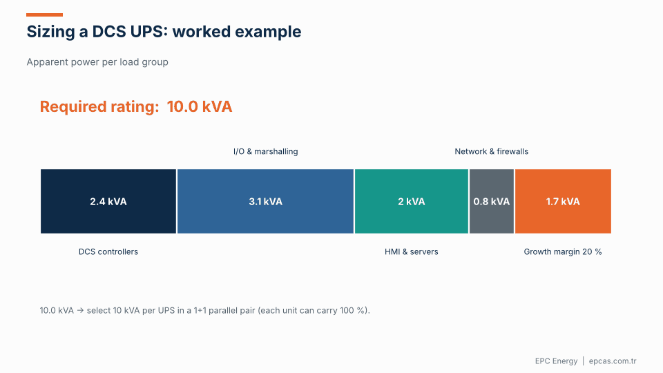
UPS sizing starts with a load list. For each group of loads, collect:
- Apparent power (kVA) or active power and power factor.
- Inrush current at switch-on.
- Number of power supplies and whether they’re redundant.
The animation shows a worked example:
- DCS controllers: 2.4 kVA
- I/O and marshalling cabinets: 3.1 kVA
- HMI workstations and servers: 2.0 kVA
- Network switches and firewalls: 0.8 kVA
- Subtotal: 8.3 kVA
- Growth margin of 20%: 1.7 kVA
- Required rating: 10.0 kVA
In a 1+1 parallel configuration, each UPS would be rated at 10 kVA, so each can carry the full load alone.
Some practical points:
Use measured data where possible. DCS vendors often provide nameplate ratings for power supplies, which can overstate actual consumption considerably. If the system already exists, measure it. If it’s new, ask the vendor for typical and maximum consumption.
Account for dual power supplies correctly. If each cabinet has two power supplies sharing the load, each supply carries about half normally, but must be able to carry all of it if the other fails. When sizing a dual-bus system, each bus must carry the full load of every cabinet.
Allow for future expansion. Control systems grow. 20% to 30% spare capacity is common in industrial specifications.
Check inrush. Switching on a cabinet with many power supplies can produce a high inrush current. The UPS must handle it without transferring to bypass or tripping.
Consider the power factor. Modern switch-mode supplies have power factors close to 1. Make sure the UPS kW rating, not just the kVA rating, is enough.
Battery autonomy

How long should a DCS UPS run on battery? The answer depends on what happens after the mains is lost.
- If there’s a standby generator, the UPS needs to cover the time until the generator starts and stabilises, plus a margin for failed starts. 10 to 30 minutes is common.
- If there’s no standby source, the UPS may need to keep the DCS alive long enough for operators to bring the process to a safe state, or for a long time in remote installations. 30 minutes to two hours is common, sometimes longer.
- For safety systems, the specification may require autonomy well beyond the normal process shutdown time.
The chart shows how autonomy varies with load for a battery sized to give 30 minutes at 100% load. Battery runtime is not linear with load. At 50% load, which is the normal condition for each UPS in a 1+1 system, the same battery lasts around 70 minutes. That’s a useful margin, but don’t count on it in the design: when one UPS fails, the other carries 100% and autonomy falls back to the design value.
Size the battery with the usual factors: ageing (typically 1.25 for end-of-life), minimum operating temperature and a design margin. And be clear in the specification about which load the autonomy refers to.
Fault clearing: the issue that catches people out

Here’s something that doesn’t come up in a load list but matters enormously. When a short circuit occurs in one branch of the UPS distribution, for example a failed power supply in one cabinet, the protective device for that branch must trip quickly enough to isolate the fault before the voltage on the whole bus collapses.
An MCB clears a short circuit on its magnetic trip, which needs a current of 3–5 times its rating for B-curve devices, 5–10 times for C-curve and 10–20 times for D-curve. That current has to come from somewhere.
On mains, there’s plenty of fault current available. But a UPS inverter is current-limited to protect its semiconductors, typically to around 2–3 times its rated current for a short time (often about 100 ms). If the inverter can’t deliver enough current to trip the branch breaker magnetically, the breaker won’t trip quickly, the bus voltage stays low, and every cabinet on the bus is affected. Eventually the UPS may shut down or transfer.
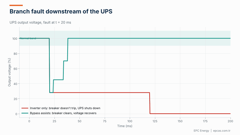
The animation compares two cases. With inverter-only fault current, the breaker doesn’t trip, the voltage stays depressed and the UPS eventually shuts down, taking the whole DCS with it. With static bypass assisting, the UPS transfers to bypass, the mains supplies enough fault current to trip the breaker within a few milliseconds, and the voltage recovers. The load on the healthy branches sees a short dip.
How to design for selective fault clearing:
- Use small branch breakers relative to the UPS rating. A 10 A B-curve MCB needs 30–50 A to trip magnetically. A 10 kVA, 230 V UPS has a rated current of about 43 A, so 2–3 times that is roughly 90–130 A, enough to trip the 10 A breaker. A 32 A C-curve MCB on the same UPS would need 160–320 A, which the inverter cannot supply.
- Use fast-acting fuses where appropriate. Semiconductor-rated or fast gG fuses clear at lower multiples.
- Keep the static bypass available for fault clearing, if the bypass supply is reliable and the protection philosophy permits it.
- Ask the UPS manufacturer for the inverter short-circuit current and its duration, and check selectivity with the distribution board designer.
- Prefer dual-bus architecture for the most critical loads, so a fault on one bus only affects one of each cabinet’s two power supplies.
This is one of the most valuable things to check during design. It’s cheap to fix on paper and expensive to fix after a plant trip.
Communication with the DCS
The UPS should report its status to the DCS so operators know when they’re on battery, in bypass, or have an alarm. Typical signals:
- Mains present, on battery, on bypass, inverter on, battery low.
- Common alarm, battery fault, overload, high temperature.
- Measurements: input and output voltage, output current and load percentage, battery voltage and current, battery autonomy remaining.
Common interfaces are Modbus RTU and TCP, Profibus or Profinet, and dry contacts for critical alarms. Hardwire the most important alarms even if you also have a data link.
Common mistakes in DCS power design
- Both power supplies in a cabinet fed from the same UPS output. The cabinet has redundant supplies, but they share one upstream breaker, so the redundancy is lost.
- Nameplate sizing. The UPS is sized on the sum of power supply nameplates and ends up running at 25% load, wasting money and efficiency.
- No selectivity study. Branch breakers are chosen by habit, and nobody checks them against the inverter’s fault current.
- Bypass from the same source as the rectifier. If that source fails, both paths fail together.
- UPS alarms not in the DCS. Operators find out the UPS is on battery when the screens go dark.
Specification checklist
When specifying a UPS for DCS and PLC systems, include:
- Load list with kVA, kW, inrush and redundancy of power supplies.
- Output voltage, frequency and phases (usually 230 V or 110 V single-phase).
- Redundancy architecture: single, 1+1 parallel, dual bus or N+1.
- Autonomy at a defined load, with ageing and temperature factors.
- Battery chemistry and location.
- Distribution: number of outgoing circuits, breaker types and ratings, selectivity study.
- Inverter short-circuit capability and bypass fault clearing philosophy.
- Environment: ambient temperature, IP rating, EMC requirements.
- Communication: protocols and signal list.
- Standards: IEC 62040, IEC 61439 for distribution, project specifications.
Frequently asked questions
What size UPS do I need for a DCS?
Add the apparent power of all DCS loads (controllers, I/O, HMI, network), using measured or vendor-typical consumption rather than nameplate where possible. Add 20–30% for growth. In a 1+1 parallel system, each UPS must be rated for the full total.
What is the best UPS redundancy for a DCS?
For most DCS installations, 1+1 parallel redundant UPS on a common output bus. For safety-critical systems such as ESD, a 2 × 100% dual-bus arrangement feeding dual power supplies is preferred.
How much battery autonomy should a DCS UPS have?
Typically 10–30 minutes if there’s a reliable standby generator, and 30 minutes to two hours or more if there isn’t, depending on how long the process needs for a safe shutdown.
Why doesn’t a breaker trip when a short circuit occurs on a UPS output?
UPS inverters are current-limited, often to 2–3 times rated current. If the branch breaker needs more current than that to trip magnetically, it won’t clear the fault quickly. Use smaller breakers, fast fuses, or rely on bypass fault clearing.
Should a DCS UPS be single-phase or three-phase?
Most DCS cabinets need single-phase 230 V or 110 V AC. Smaller systems use single-phase UPS output directly. Larger systems may use three-phase UPS with single-phase distribution, balancing loads across phases.
Control system power from EPC Energy
EPC Energy designs and builds industrial UPS systems for DCS, PLC and safety systems in power plants, oil and gas and process industries, with parallel redundant and dual-bus configurations, selective distribution, and Modbus, Profinet and IEC 61850 communication. Our static transfer switches complete dual-source designs. Read our comparison of STS vs ATS and the ITIC curve, then send your load list to epcas@epcas.com.tr.