

Static Voltage Regulator vs Servo Stabilizer: Which One for High-kVA Industrial Loads?
Ask for a quotation for a 500 kVA voltage stabilizer and you will usually receive two very different machines. One is a servo stabilizer: a motor-driven variable transformer that slides a carbon brush along a winding to adjust the output. The other is a static voltage regulator: no moving parts, with power semiconductors switching or modulating a correction voltage under DSP control.
On paper both promise a stable output from an unstable supply. In service they behave very differently, especially at high power, on fast-changing loads, and in places where maintenance visits are expensive. This article compares the two technologies on the parameters that matter, explains how the buck-boost topology lets a static voltage regulator stay compact at high kVA, and draws on two of our own projects: an 800 kVA regulator for a port in Sudan and a 30 kVA regulator for a power plant’s internal supply in Egypt.
Our Voltage Regulator range keeps output voltage steady when the incoming supply fluctuate
How a Servo Stabilizer Works?
A servo stabilizer is built around a variable autotransformer, often called a variac. A servo motor drives a carbon brush across the exposed turns of the winding. A control card measures output voltage and turns the motor in whichever direction brings the output back to setpoint. The variac usually feeds a buck-boost transformer in series with the load, so the variac only handles the correction power.
The design is simple, tolerant of overload and cheap at low and medium power. Its limits come from the mechanism itself:
- Correction depends on how fast the motor can drive the brush. Typical figures are 10 to 50 volts per second. A 40 V sag takes somewhere between 0.8 and 4 seconds to correct.
- Brushes, gears, motor bearings and the winding track all wear. Dust and humidity accelerate this.
- On a load that switches frequently, the motor never settles and the brush keeps moving, which accelerates wear on one section of the track.
If you are new to the topic, our guide on What is Three Phase Voltage Regulator explains how these units work on three-phase networks.
How a Static Voltage Regulator Works?
A static voltage regulator replaces the moving brush with power electronics. There are two main approaches.
- Thyristor tap switching. Static switches select taps on a transformer winding. Correction happens in discrete steps, typically in one or two mains cycles.
- PWM buck-boost (IGBT). An IGBT converter generates a correction voltage of variable magnitude and polarity, injected in series with the supply through a buck-boost transformer. Correction is continuous and stepless.
In both cases a DSP measures each phase independently, many times per cycle, and adjusts the correction for each phase on its own. That last point is important for unbalanced supplies. Many servo designs regulate all three phases from a single averaged measurement.
Buck-boost topology: only the correction voltage passes through the series transformer, so the converter is rated at a fraction of load kVA.

The Buck-Boost Principle: Why It Matters at High kVA
The buck-boost topology is the reason a static voltage regulator can be physically small at high power. The series transformer does not carry the full load power through a conversion stage. It only adds or subtracts the correction voltage.
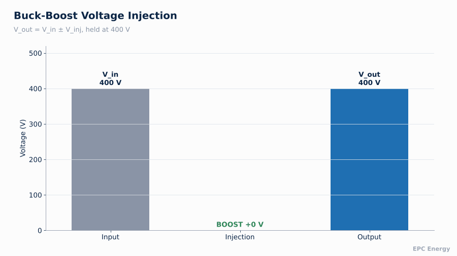
The output voltage is simply:
V_out = V_in ± V_inj
If the regulator must correct an input range of ±20%, the injection transformer and converter only need to handle about 20% of load kVA. An 800 kVA regulator with a ±20% range has a power path of roughly 160 kVA. The remaining 640 kVA flows straight through the series winding with very low loss.
This is how the 800 kVA regulator we built for a port facility in Sudan fits into a 700 × 700 × 2000 mm enclosure. A full-power transformer or double-conversion approach at 800 kVA would need several times that footprint.
Buck-boost injection in action: as the input moves, the injected voltage changes magnitude and polarity so the output stays at setpoint.
Head-to-Head Comparison
| Parameter | Servo stabilizer | Static voltage regulator |
| Correction method | Motor-driven brush on variac | Thyristor taps or IGBT PWM injection |
| Correction speed | 10–50 V/s | Within 1–2 cycles (20–40 ms at 50 Hz) or faster |
| Output accuracy | ±1% to ±3% | ±0.5% to ±1% |
| Per-phase control | Often averaged | Independent per phase |
| Moving parts | Motor, gears, brush | None (fans only) |
| Maintenance | Brush and track inspection, cleaning | Fan and filter checks |
| Behaviour on fluctuating loads | Hunting, brush wear | No mechanical penalty |
| Footprint at 500+ kVA | Large | Compact with buck-boost |
| Initial cost | Lower | Higher |
Response Time: What It Means for Your Load
Correction speed is the number that separates the two technologies most clearly, and also the one that is easiest to misread on a datasheet.
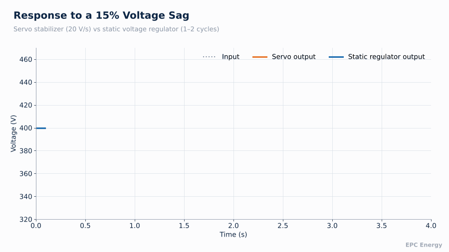
Consider a crane starting at a port, pulling the supply down by 15% for two seconds. With a servo stabilizer correcting at 20 V/s, a 35 V dip takes almost two seconds to recover. By then the crane has finished accelerating and the voltage is rising again, so the servo now overshoots in the other direction. Connected equipment sees a long sag followed by a surge.
A static voltage regulator corrects the same sag within one or two cycles. Equipment downstream sees a disturbance shorter than most drives and PLC power supplies will notice.
Same voltage sag, two responses: the servo stabilizer ramps slowly and overshoots, the static voltage regulator corrects within a cycle or two.
Where Each Technology Makes Sense
Servo stabilizers are reasonable when:
- Power is low to medium and cost is the main driver
- Supply variation is slow, such as daily drift on a rural feeder
- The site has regular maintenance access
- Loads are mostly resistive or steady
Our Sudan 800kVA SVR project shows how a DSP-controlled compact static voltage regulator was designed and built for a marine application.
Static voltage regulators are the better choice when:
- Loads switch frequently: cranes, welding, compressors, elevators
- Equipment is sensitive: drives, automation, medical, telecom
- The site is remote or maintenance visits are costly
- Supply is unbalanced and each phase needs its own correction
- Space is tight at high kVA
- The regulator protects critical infrastructure where a failure is not an option
Input-output characteristic: inside the regulating window the output stays within ±1% of setpoint; outside it the regulator protects the load or transfers to bypass.

Reference Projects
800 kVA Static Voltage Regulator, Port Facility (Sudan, 2025)
Port and ship power systems combine everything a stabilizer dislikes: weak grids, large motor loads, crane starts and shore connections that change load in large steps. The regulator we designed for this project is DSP-controlled, uses the buck-boost architecture described above and fits 800 kVA into a 700 × 700 × 2000 mm cabinet. The small footprint mattered as much as the performance, because it had to fit into an existing electrical room.
The Egypt 30kVA SVR project covers a static voltage regulator designed and manufactured for a power plant’s internal consumption.
30 kVA Static Voltage Regulator, Power Plant Internal Consumption (Egypt, 2022)
A power plant’s internal consumption circuits feed critical auxiliaries: controls, instrumentation, protection. In this project we designed and manufactured a 30 kVA industrial static voltage regulator with a bypass transformer, so that the critical loads remain supplied even while the regulator itself is being serviced.
Specification Checklist
When requesting a quotation for a static voltage regulator, define:
- Rated power (kVA) and power factor of the load
- Input voltage range to be corrected, e.g. ±15% or ±20%
- Output accuracy, e.g. ±1%
- Required response time
- Per-phase or averaged regulation
- Bypass: static, manual or with bypass transformer
- Ambient temperature, altitude, IP rating
- Communication: Modbus RTU, Modbus TCP/IP, SNMP or Profinet
- Physical constraints: footprint, cable entry, transport limits
An unbalanced input range should be stated explicitly. “±20%” on a supply where one phase sags while another swells is a harder requirement than the same figure on a balanced feeder.
Unbalanced Supplies and Per-Phase Regulation
Industrial supplies are rarely balanced. Single-phase loads, long feeders and transformer tap differences leave one phase several percent lower than the others. A servo stabilizer that measures one phase, or the average of three, drives all three variacs together. If phase L1 is at 200 V while L2 and L3 sit at 230 V, an averaging controller corrects the three of them toward the mean and leaves L1 under-voltage and the others over-voltage.
A static voltage regulator with three independent injection stages measures and corrects each phase separately. In the same situation, it boosts L1 by 30 V and leaves L2 and L3 close to untouched. Three-phase motors benefit most from this. A voltage imbalance of only 2% can produce a current imbalance several times larger, with heating that shortens motor insulation life.
Unbalanced supply: averaged correction leaves one phase low and two high, while per-phase static regulation brings all three phases to setpoint.

Bypass Arrangements
Every voltage regulator eventually needs to be serviced, and the load must stay supplied when that happens. Three bypass options are common:
- Static bypass: an electronic switch transfers the load to the raw supply automatically if the regulator develops a fault
- Manual maintenance bypass: a make-before-break switch isolates the regulator completely for service
- Bypass transformer: used where the raw supply voltage is not acceptable to the load even for a short time, so the bypass path itself provides a fixed voltage adjustment
For critical auxiliaries, as in our Egypt project, the bypass transformer arrangement keeps the load inside its acceptable window even during maintenance.
Ships and offshore vessels rely on stable onboard power, which is why our work in the Marine & Ship sector focuses on voltage regulation for those systems.
Efficiency and Losses
A common objection to static regulators is efficiency. With the buck-boost topology this objection mostly disappears, because the main power path is only the series winding. Well-designed static voltage regulators reach efficiencies above 98% at rated load. The comparison to make is at the operating point where the regulator spends most of its life, usually 40 to 70% load with a moderate correction, not at maximum correction.
Why We Build Static Voltage Regulators to Specification
Off-the-shelf regulators are built for a nominal supply and a typical load. Industrial projects rarely deliver either. At EPC Energy we design static voltage regulators around the actual input range, load profile, physical space and communication requirements of each site. Every unit is tested at full load before shipment, including step-response tests at the edges of the regulating range.
Send us your supply data, load list and room dimensions, and our engineers will propose a regulator design.
Frequently Asked Questions
Is a static voltage regulator better than a servo stabilizer?
For fast-changing or sensitive loads, yes. A static regulator corrects within one or two cycles, has no moving parts and regulates each phase independently. A servo stabilizer can still be the lower-cost choice for slow variations and steady loads.
How fast does a static voltage regulator respond?
Typically within one to two mains cycles, 20 to 40 ms at 50 Hz. IGBT-based designs can respond faster.
Why is a buck-boost voltage regulator so compact?
Only the correction voltage passes through the converter and series transformer. With a ±20% range, the power stage is rated at about 20% of the load kVA.
Does a static voltage regulator need maintenance?
Very little. There are no brushes or motors. Routine checks cover cooling fans, filters and connections.