

Earth Leakage Detection in Unearthed DC Systems

Most industrial DC auxiliary systems in substations, power plants, railways and ships are deliberately left unearthed. Neither the positive nor the negative pole is connected to earth. The system floats.
The reason is availability. In an earthed system, a single insulation fault is a short circuit: a fuse blows and part of the system goes dead. In an unearthed system, a single insulation fault creates no closed path, so no fault current flows and everything keeps working. Protection relays still trip breakers, control circuits still run, the battery still supports the bus.
That advantage comes with a condition. The first fault must be found and repaired before a second one appears. A second fault on the other pole, or in the wrong place in a control circuit, can cause anything from a blown fuse to a circuit breaker tripping without command. Continuous DC earth fault detection is what turns an unearthed DC system from a hidden risk into a reliable one. This article explains how DC earth fault detection methods work, where each one is blind, how to set alarm thresholds and how to find a fault once it is detected.
Browse the Industrial Rectifier category to find units sized for a steady DC bus.
What Happens When an Insulation Fault Appears
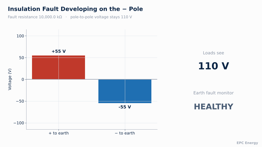
Picture a 110 V DC system with no earth connection. Through the natural insulation resistance of cables and equipment, both poles settle at roughly symmetrical voltages relative to earth: about +55 V and -55 V.
Now insulation on a negative conductor deteriorates. Water gets into a junction box, or a cable sheath is damaged. The negative pole develops a resistive path to earth.
- The negative pole is pulled toward 0 V relative to earth
- The positive pole moves toward +110 V relative to earth
- The voltage between the poles does not change at all
Every load still sees 110 V and keeps running. Nothing in the system notices the fault unless something is specifically measuring the pole-to-earth voltages or the insulation resistance.
As insulation on the negative pole deteriorates, the negative pole moves toward earth potential and the positive pole rises toward full system voltage, while the pole-to-pole voltage stays at 110 V.
The Danger of the Second Fault
With the first fault in place, the system has effectively become earthed at an unknown point. Two scenarios make the second fault dangerous:
Short circuit. A second fault on the opposite pole closes a loop through earth. Current flows, limited only by the fault resistances. A fuse or breaker may trip and take out an entire distribution circuit.
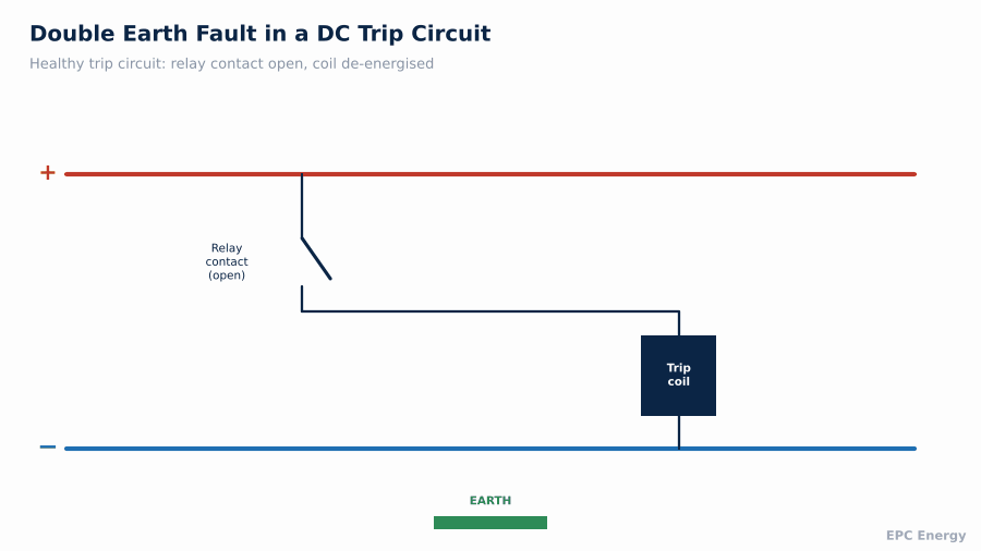
Spurious operation. This is the scenario that worries protection engineers. Consider a trip circuit: positive pole, relay contact, wire to the breaker trip coil, negative pole. Suppose the first fault has put the positive pole at earth potential. Now a second fault develops on the wire between the open relay contact and the trip coil, connecting it to earth. That wire is now effectively connected to the positive pole. The trip coil energises and the circuit breaker opens, with no protection command. In a substation or power plant, an unwanted trip can be as damaging as a failure to trip.
Two earth faults combine to bypass an open relay contact: current flows through earth and the trip coil operates without any protection command.
Cable capacitance adds a further risk. Long control cables have significant capacitance to earth. When an earth fault appears or disappears, these capacitances discharge through whatever path is available, including sensitive relay inputs. This is why modern binary inputs on protection relays have minimum operating energy requirements, and why fast detection matters.
Grounding arrangements such as TN, TT and IT systems change how a rectifier must be wired, and What is TN, TT and IT Systems explains each one.
Method 1: The Balanced Bridge
The simplest and most common detection method connects two equal, high-value resistors from the positive and negative poles to earth, forming a bridge. A voltage sensor measures the potential of the bridge midpoint relative to earth.
- Healthy system: both poles sit at half system voltage relative to earth, the midpoint is at earth potential, and the sensor reads zero
- Fault on one pole: the balance shifts, the midpoint moves away from earth, and the sensor measures a voltage proportional to the fault severity
The direction of the shift tells you which pole is faulty, and the magnitude, combined with the bridge resistor values, gives an estimate of the fault resistance.
Balanced bridge method: equal resistors from each pole to earth, and a sensor measuring the midpoint voltage. An insulation fault on either pole unbalances the bridge.

Pole-to-earth voltages on a 110 V system as the fault resistance on the negative pole falls. Below a few kilohms, the faulty pole is effectively at earth potential.

The balanced bridge has one important blind spot: symmetrical faults. If insulation deteriorates equally on both poles, which happens with general moisture ingress or ageing across a whole cable route, the bridge stays balanced and the sensor reads nothing. The system can have a very low overall insulation resistance and the bridge will not see it.
A DSP-controlled 30A unit built for a UK transport customer is described in our UK 125VDC SD Series project.
Method 2: Signal Injection
Insulation monitoring devices (IMDs) built to IEC 61557-8 solve the symmetrical fault problem by actively measuring insulation resistance. They inject a low-frequency AC or pulsed DC measuring signal between the system and earth, then measure the resulting current. The ratio gives the insulation resistance directly, regardless of which pole is affected or whether both are.
Injection IMDs:
- detect symmetrical and asymmetrical faults equally
- report a resistance value in kilohms, which can be trended
- must account for system capacitance, which slows the measurement on large systems
- must not be combined with a second IMD on the same galvanically connected system, as the two would measure each other
Many installations use both methods: a bridge for fast detection of asymmetrical faults and pole identification, and an injection IMD for accurate resistance measurement.
Setting Alarm Thresholds
Most schemes use two levels:
- Pre-warning: a higher resistance value that triggers maintenance attention before the fault is serious
- Alarm: a lower value at which the fault should be located and repaired with priority
The right values depend on system voltage, system size and the sensitivity of the loads. The key check is whether the resulting earth fault current could operate the most sensitive relay or binary input in the system. Thresholds should be set well above that point. Trending is more useful than any single setting: insulation that falls steadily over weeks is a cable route taking on water, which is far better fixed in a planned outage than discovered during a storm.
Trending insulation resistance with two thresholds. A steady decline gives weeks of warning before the alarm level is reached.

Finding the Fault
Detection says that a fault exists. Location says where. On a system with hundreds of outgoing circuits, finding a high-resistance fault by switching circuits off one at a time is slow and disruptive, and in a substation may not be acceptable at all.
Insulation fault location systems to IEC 61557-9 use the injection signal from the IMD and measuring current transformers on each outgoing feeder. The feeder carrying the injected signal is the faulty one. Portable versions with clamp-on sensors are used where fixed sensors are not justified.
Sizing a charger for a substation’s 110V battery bank becomes simpler when you follow the steps in our 110V DC Battery Charger for Substations procurement guide.
Common Sources of DC Insulation Faults
Experience across substations and plants shows the same culprits again and again:
- Outdoor junction boxes and marshalling kiosks where condensation collects and terminals corrode
- Cable glands and entries that were not resealed after modification work
- Trackside or yard equipment exposed to rain, ballast dust and mechanical damage
- Space heater and lighting circuits fed from the DC system, which are often less carefully installed than protection wiring
- Battery rooms, where electrolyte spray on racks and terminals creates conductive paths
Faults often follow the weather. Insulation resistance that falls every time it rains and recovers in dry weather points to an outdoor location with water ingress, and the trend log will show the pattern long before the fault becomes permanent.
Integrated Detection in the Rectifier
Earth leakage detection can be a separate device, or it can be built into the rectifier or battery charger. The integrated approach has practical advantages: the rectifier already has a controller, display and communication interface, so alarms appear on the same screen and travel over the same Modbus or IEC 61850 link as rectifier and battery alarms.
The SD Series 125 V DC, 30 A industrial rectifier we supplied for a UK transportation project includes an internal earth leakage detection module for exactly this reason. It monitors both poles continuously, identifies the faulty pole and reports through the rectifier’s own alarm system. It also uses DSP control and a two-stage diode dropper to keep load voltage within limits during boost charging.
Facilities that generate electricity can review how DC supply equipment fits their plant through our Power Plants sector page.
Systems with Multiple Rectifiers and Bus Ties
Larger DC systems often have two rectifiers, two batteries and a bus coupler. Each half may have its own detection, which is fine while the halves are separated. When the bus coupler closes, the two halves become one galvanically connected system. Two bridges in parallel halve the bridge resistance seen by the system, and two injection IMDs on the same system will interfere with each other.
The solution is logic that disables one detector when the coupler is closed, using an auxiliary contact on the coupler. It is a small detail, and one that is frequently missed during commissioning. The same applies to any temporary connection between systems, such as a portable charger used during battery maintenance: its own detection, if fitted, must be considered before it is connected to a live bus.
Specification Checklist
- System voltage and whether the system is unearthed, earthed or mid-point earthed
- Detection method: bridge, injection or both
- Pre-warning and alarm thresholds, adjustable on site
- Pole identification
- Fault location requirement: none, portable or fixed per feeder
- Total system capacitance, for correct IMD selection
- Alarm outputs: relay contacts, Modbus, IEC 61850
- Integration in the rectifier or a separate device
How EPC Energy Approaches DC System Protection
We design rectifiers and battery chargers for substations, power plants, railways and marine systems, most of which operate unearthed. Earth leakage detection, with pole identification and remote alarms, can be integrated into the rectifier and is tested as part of the factory acceptance test.
Send us your DC system voltage and the type of loads it feeds, and our engineers will propose the right detection scheme.
Frequently Asked Questions
Why are DC auxiliary systems left unearthed?
So that a single insulation fault does not cause a short circuit. The system keeps running and the fault can be repaired in a planned way.
What is the risk of a second earth fault?
A second fault can cause a short circuit between poles or bypass an open relay contact and trip a circuit breaker without command.
Can a balanced bridge detect all earth faults?
No. A symmetrical fault with equal deterioration on both poles keeps the bridge balanced. An injection-type insulation monitoring device detects it.
Can earth leakage detection be built into the rectifier?
Yes. Integrated detection reports alarms through the rectifier’s own display and communication interface.