

Dropper Diodes in DC Systems: Keeping Load Voltage Safe During Boost Charge

A nickel-cadmium battery on a 110 V DC system does not sit at 110 V. Fully charged and floating, a typical 92-cell string sits at about 129 V. During boost or commissioning charge, it climbs above 142 V. Near the end of a long discharge, it falls to around 101 V.
The loads connected to that system, such as protection relays, circuit breaker coils, control equipment, emergency lighting, have a much narrower comfort zone, typically 110 V ±10%: 99 V to 121 V. Something has to bridge the gap between what the battery needs and what the load can accept.
In a large share of industrial DC systems, that something is a dropper diode: a chain of silicon diodes placed in series between the battery bus and the load bus, switched in and out by contactors. It is an old technique, and a surprisingly effective one. This article explains how dropper diodes work, how to size single- and two-stage designs, what they cost in heat, and where they fail. We draw on two of our projects: the SD Series 125 V DC rectifier with a two-stage dropper supplied to the UK, and a 24 V DC rectifier with single-stage dropper topology for a data centre in Turkey.
Our Industrial Rectifier listings let you compare output ratings side by side before choosing a model.
The Problem: Battery Voltage Window vs Load Voltage Window
Take a 110 V system with 92 NiCd cells:
| Battery state | V/cell | String voltage |
| Boost / commissioning charge | 1.55 | 142.6 V |
| Float charge | 1.40 | 128.8 V |
| End of discharge | 1.10 | 101.2 V |
The battery voltage range is 101 V to 143 V. The load accepts 99 V to 121 V. Float alone is already above the load limit, and boost is more than 20 V above it.
Why not use fewer cells, so float voltage sits inside the load window? Because then the end-of-discharge voltage falls below the load minimum. A 78-cell string floats at 109 V but ends its discharge at 86 V. Cell count is chosen for the bottom of the window. The dropper takes care of the top.
Our piece on the Industrial Battery Charger manufacturer explains how these chargers are built to keep battery banks topped up.
How a Dropper Diode Works?
A forward-biased silicon diode drops a fairly constant voltage, around 0.7 to 1.0 V depending on current and temperature, almost regardless of the current through it. Put ten in series and you have a drop of roughly 8 to 10 V that behaves like a fixed voltage source in the opposite direction.
A dropper stage is a diode chain with a contactor in parallel. When the contactor is open, load current flows through the diodes and the load sees battery voltage minus the stage drop. When the contactor closes, it short-circuits the diodes and the load sees full battery voltage. The controller decides which stages are bypassed based on the measured bus voltage.
Two-stage dropper: each diode chain has a bypass contactor. The controller closes or opens contactors so the load bus stays inside its voltage window.

Single-Stage vs Two-Stage Design
With one stage, the controller can choose between two load voltages: battery voltage, or battery voltage minus one fixed drop. With two stages of different sizes, it has up to four combinations, which allows much finer tracking of the battery voltage.
A two-stage design for our 92-cell example might use Stage 1 at 10 V and Stage 2 at 12 V:
| Battery state | Battery voltage | Stages in circuit | Load voltage |
| Boost | 142.6 V | S1 + S2 (22 V) | 120.6 V |
| Float | 128.8 V | S1 (10 V) | 118.8 V |
| Early discharge | 120 V | none | 120 V |
| End of discharge | 101.2 V | none | 101.2 V |
The load stays between 101 V and 121 V throughout.
A single-stage design for the same battery would need one stage large enough to handle boost (about 22 V), which would then pull the load too low at float voltage (128.8 − 22 = 106.8 V). That is inside the window, but uncomfortably close to the bottom, with less margin for cable voltage drop. In practice single-stage droppers suit systems with a narrower battery voltage range, or where boost charging is rare. That is why our 24 V DC data centre system in Turkey uses a single stage, while the 125 V DC UK system uses two.
Control logic and a 125VDC rating are the focus of the UK 125VDC SD Series project case.
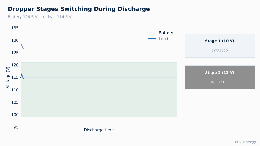
Battery voltage across boost, float and discharge, and the load voltage produced by switching dropper stages in and out.

As the battery discharges, the controller bypasses dropper stages one at a time so the load voltage stays inside its window.
Switching Thresholds and Hysteresis
Each stage needs a bypass threshold and a reinsertion threshold. If both are set at the same voltage, the stage will chatter when battery voltage sits near the setting, wearing the contactor and creating step changes on the load bus.
Typical practice:
- Bypass a stage when load voltage falls to a lower limit, for example 108 V
- Reinsert the stage when load voltage would rise to an upper limit, for example 120 V, with the stage in circuit
- Add a short time delay to ignore transients such as breaker closing currents
The gap between thresholds must be larger than the stage voltage. Otherwise inserting the stage immediately takes load voltage below the bypass threshold, and the controller oscillates.
A compact 24V, 25A rectifier installed for a Turkish data center is covered in the Turkey 24V 25A data center rectifier project.
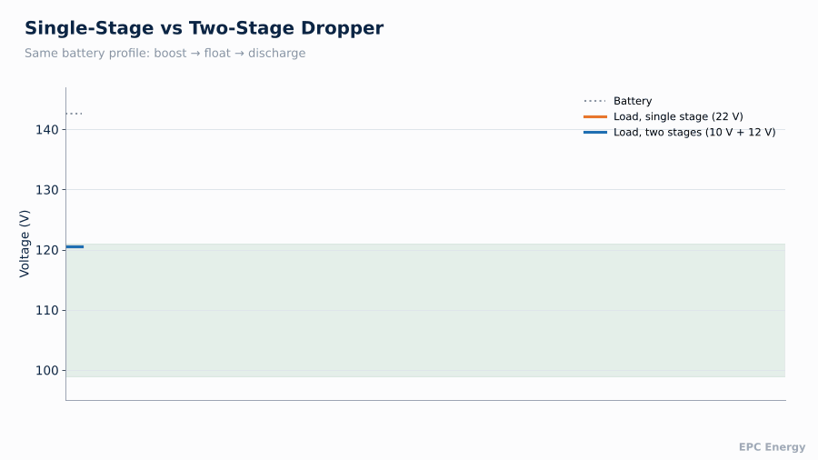
The same battery profile with a single-stage and a two-stage dropper. Two stages track the battery more closely and keep load voltage in a tighter band.
Heat: The Price of a Dropper
A dropper converts the voltage it drops directly into heat. The power is simply:
P = V_drop × I_load
With 22 V dropped at 30 A load, the dropper dissipates 660 W. At 60 A, 1,320 W. That heat must be removed by heatsinks and cabinet ventilation.
Heat dissipated in the dropper for different stage combinations and load currents. Cabinet thermal design must handle the worst case.

In practice the worst case is short and rare. Boost charge, when both stages are in circuit, typically happens only after a deep discharge or during commissioning. During normal float operation, only one stage is active, at lower dissipation. But the cabinet must still be designed for the worst case at maximum ambient temperature, and diodes must be selected with derating for junction temperature.
Failure Modes and Fail-Safe Design
Silicon diodes usually fail short-circuit. A shorted diode in a chain reduces the stage drop by about 0.8 V, which is a minor inconvenience rather than a hazard. An open-circuit diode is rarer but far more serious: it breaks the path between battery and load.
The bypass contactors are the safeguard. A well-designed dropper uses contactors arranged so that loss of control power closes them, bypassing all stages. The load then sees full battery voltage, which may be high during boost, but it stays supplied. For a protection system, a slightly high voltage is a much smaller risk than no voltage. The contactor state should also be monitored, so that a contactor which fails to close is reported.
Other good practice:
- Monitor load bus voltage independently of the battery bus
- Alarm if load voltage leaves its window for longer than a set time
- Size diodes and contactors for the maximum short-circuit current the battery can deliver through the load bus
Sizing the Diode Chain
Three numbers decide the diode chain: stage voltage, continuous current and surge current.
Stage voltage. The number of diodes per stage is the required drop divided by the forward voltage per diode at the expected current and temperature. Forward voltage falls as temperature rises, by roughly 2 mV/°C per diode, so a chain that drops 10 V cold may drop 9 V hot. Size for the warm condition, since that is where the drop is smallest and the load voltage highest.
Continuous current. Diodes must carry maximum load current continuously with a junction temperature well below the limit at the highest cabinet temperature. In practice, this means press-pack or stud-mounted diodes on a common heatsink, derated to around 50 to 60% of their catalogue current.
Surge current. When a downstream fault occurs while a stage is in circuit, the full battery short-circuit current flows through the diode chain until the protective device clears. The diodes’ surge rating (I²t) must exceed what the battery can deliver for that clearing time. This is the check most often skipped, and the one that decides whether a downstream fault takes out the dropper as well.
Choosing the right charge capacity for a substation starts with the sizing tables in our 110V DC Battery Charger for Substations guide.
Testing a Dropper at the Factory
A dropper is only proven by operating it. At our facility, every dropper-equipped charger is tested by driving the battery bus through its full voltage range, from end of discharge to boost, at rated load current. We record the load bus voltage at each stage change, verify thresholds and time delays, confirm fail-safe bypass on loss of control power, and run a heat test with all stages in circuit at full current.
Alternatives to Dropper Diodes
Droppers are not the only solution. Alternatives include:
- Separate load and battery rectifiers, where the battery charger never feeds the load directly
- Continuous voltage regulators using thyristors or switch-mode converters between battery and load bus
- Restricting boost charge to times when loads can be supplied from elsewhere
Each has a cost. Continuous regulators add electronics and, in some designs, a new single point of failure. Separate rectifiers add capital cost. The dropper’s appeal is its simplicity: diodes, contactors and a straightforward control logic that maintenance staff can understand and test.
Specification Checklist
- Battery chemistry, number of cells, float, boost and end-of-discharge voltages
- Load voltage window
- Maximum load current during boost
- Single or two-stage, based on the voltage ranges
- Thermal design for maximum ambient temperature
- Fail-safe contactor arrangement and monitoring
- Alarms to SCADA
How EPC Energy Builds DC Systems with Droppers
We design battery chargers and rectifiers with integrated single- and two-stage dropper diodes for substations, railways, power plants and data centres. Dropper switching, thresholds and fail-safe behaviour are verified during factory acceptance testing at full load current.
Send us your battery and load data, and our engineers will size the dropper stages and thermal design.
Frequently Asked Questions
What is a dropper diode?
A chain of series diodes between battery bus and load bus that reduces load voltage by a fixed amount when the battery voltage is high, during float or boost charge.
Why does a 110V DC system need a dropper?
The battery voltage ranges from about 101 V to over 142 V, while loads accept roughly 99 V to 121 V. The dropper reduces the high end.
What is the difference between single and two-stage droppers?
Two stages give more voltage combinations, so the load voltage follows the battery more closely and stays in a tighter band.
What happens if a dropper diode fails?
Diodes usually fail short, which slightly reduces the drop. Bypass contactors are arranged to close on control failure so the load stays supplied.