

3-Pole vs 4-Pole Static Transfer Switch: Neutral Switching Explained

A static transfer switch moves a critical load from one AC source to another in a quarter of a cycle. Most discussions of STS focus on that speed: thyristor switching, transfer time, the ITIC curve. We have covered those topics in our STS vs ATS article.
This article is about a decision that comes earlier in the design and is often made by default: does the STS switch three poles or four? In other words, does the neutral transfer along with the phases, or stay solidly connected to both sources?
It sounds like a detail. It is actually an earthing question, and getting it wrong creates problems that do not show up during commissioning: neutral current flowing on earth conductors, ground-fault protection that trips for no visible reason, or that fails to trip when it should. The reference project for this article is a set of two 3-phase, 3 × 208 V, 400 A, 4 pole static transfer switches we designed and manufactured for one of the most prominent oil and gas refineries in Bahrain.
When one power source drops out, a Transfer Switch shifts the load to the backup feed.
Why the Neutral Matters at All
A three-phase load with no neutral, such as a motor or a three-phase rectifier, does not care how many poles the STS has. The question only arises when the loads downstream of the STS need a neutral. That is the case for any 4-wire system feeding single-phase loads: 208Y/120 V or 400/230 V distribution to control panels, instrumentation, lighting and IT equipment.
The Bahrain refinery STS units operate on a 208 V three-phase system, the US-style 208Y/120 V arrangement, where single-phase 120 V loads connect from phase to neutral. The neutral carries real load current and must go somewhere.
Separately Derived Sources
The key concept is the separately derived source: a source whose neutral has no direct electrical connection to the neutral of another source. A dedicated transformer, a generator and a UPS with an isolated output are typical examples.
In TN-S and similar earthing systems, each separately derived source has its own neutral-to-earth bond, located at the source. That bond is what makes earth-fault protection work: fault current flows from the phase, through the earth conductor, back to the bond and into the neutral of the source.
The earthing rule for installations with multiple sources is simple in principle. Neutral and earth must be bonded at exactly one point in each system. IEC 60364-4-44 states this for multiple-source TN systems, and the equivalent rules for separately derived systems appear in NEC Article 250.30.
Transfer time decides much of the STS vs ATS article comparison, since the ITIC curve shows how much interruption sensitive equipment can tolerate.
What Goes Wrong with a 3-Pole STS
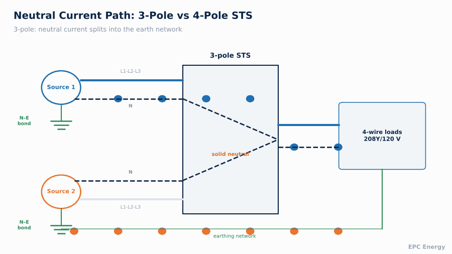
Now imagine two separately derived sources, each with its own neutral-earth bond, feeding a 3-pole STS. The phases are switched. The neutral is not: it is a solid busbar connected to both source neutrals at the same time.
The two neutral-earth bonds are now connected in parallel through the shared neutral and through the earth conductors. Load neutral current, which should return only along the neutral conductor, now splits. Part of it returns along the neutral. Part of it flows through the earth conductors, between the two bonding points.
With a solid neutral and two bonded sources, part of the load neutral current returns through the earth conductors, creating an objectionable current path.

This parallel path has three consequences:
- Objectionable current on earth conductors. Earthing conductors, cable armour, conduits and structural steel carry continuous current. That creates heating, corrosion risk and voltage differences between earthed parts. In a refinery with hazardous areas, unexplained current on bonding conductors is not acceptable.
- Ground-fault protection errors. Ground-fault protection (GFP) on each source measures the residual current at that source. When load current splits between neutral and earth, the protection sees an imbalance even with no fault and may trip. Worse, a real earth fault may be split between the two sources and neither relay sees enough current to trip.
- Electromagnetic interference. Currents in the earth network create magnetic fields and noise on instrumentation cables that share cable trays.
With a 3-pole STS, neutral current splits between the neutral conductor and earth. With a 4-pole STS, only the active source’s neutral is connected and current returns only along the neutral.
How a 4-Pole STS Solves It
A 4-pole static transfer switch switches the neutral together with the three phases. At any moment, the load neutral is connected to only one source neutral, the one currently supplying the load. The other source’s neutral, with its own earth bond, is disconnected.
Plants that run around the clock often specify an Industrial Transfer Switch rated for continuous duty.
Result: there is always exactly one neutral-earth bond in the active circuit. Neutral current returns along the neutral. GFP on each source sees only that source’s current. Earth conductors carry fault current only, which is what they are there for.
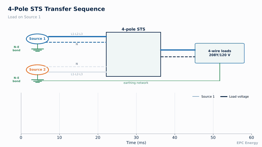
4-pole STS: phases and neutral switch together, so the load is always connected to one source and one neutral-earth bond.

Neutral Switching and Transfer Timing
In a mechanical 4-pole transfer switch, the neutral pole is often arranged to make before it breaks, or to overlap. In a static switch, neutral switching uses thyristors just like the phase poles.
A typical STS transfer sequence:
- The controller detects a disturbance on the preferred source, usually within 1 to 2 ms
- Gating is removed from the thyristors of source 1, phases and neutral
- The controller confirms that current in source 1 thyristors has stopped (break-before-make)
- Thyristors of source 2 are gated, phases and neutral
- Total transfer time typically falls within a quarter cycle, around 4 to 6 ms
Break-before-make on all four poles prevents the two sources from being paralleled, even momentarily. That is particularly important where the sources are not synchronised. The controller should also check the phase angle between the sources before a planned transfer and block it if the difference is outside the allowed window, typically ±15°.
STS transfer timing: detection, turn-off of source 1, current-zero confirmation and turn-on of source 2, all within about a quarter cycle.

Source 1 fails, the STS removes it on all four poles, confirms current zero and connects source 2. The load sees a sub-cycle interruption.
When You Can Use a 3-Pole STS
A 3-pole STS is perfectly acceptable in several situations:
- Three-wire loads. No neutral is distributed downstream.
- Common neutral sources. Both sources share a single neutral-earth bond, for example two feeders from the same transformer.
- Isolation transformer downstream. The STS switches three phases into a transformer, and the transformer secondary creates a new separately derived system with its own single bond. This arrangement is common in data centres and is often used with 3-pole STS at the primary side.
The question to ask at the design stage is: how many neutral-earth bonds would be connected together if the neutral were solid? If the answer is more than one, a 4-pole STS or a downstream isolation transformer is required.
A 400A four-pole static transfer switch supplied to a Bahraini refinery is the subject of the Bahrain 4-pole STS project.
4-Pole Design Considerations
Switching the neutral adds its own requirements:
- Neutral pole rating. With non-linear single-phase loads, triplen harmonics add in the neutral. Neutral current can exceed phase current, so the neutral pole may need a higher rating than the phases.
- Neutral pole protection. Neutral thyristors need the same fuse or overcurrent coordination as phase thyristors.
- Loss of neutral. A failed neutral pole that opens leaves single-phase loads with floating neutral and unbalanced voltages. Monitoring of the neutral pole state is essential.
- Maintenance bypass. The bypass must also be 4-pole, so the earthing arrangement is preserved during maintenance.
A Worked Example: Where the Current Goes
Consider a 208Y/120 V system feeding 300 A of single-phase loads, unevenly spread across the phases, so that 80 A flows in the neutral. Two transformers feed a 3-pole STS, each bonded at its own star point. The neutral is solid through the STS.
The neutral current now has two parallel return paths to the active source: the neutral conductor itself, and the earth path through the second transformer’s bond and the earthing network back to the first. Current divides in inverse proportion to the impedance of each path. If the earth path is only five times the impedance of the neutral, around 13 A of the 80 A flows through the earth network continuously, with no fault anywhere in the system.
A ground-fault relay on the active source set at 10 A would see that 13 A as an earth fault and trip the source, causing exactly the outage the STS was installed to prevent. If the relay is desensitised to avoid nuisance trips, it no longer protects against real faults. Neither outcome is acceptable. A 4-pole STS removes the parallel path entirely, and the problem disappears.
Refineries and gas facilities cannot afford unplanned outages, and our Oil and Gas sector page outlines the switching equipment we supply for them.
Hazardous Area Context
In oil and gas facilities, the earthing network does more than carry fault current. It equalises potential between equipment in areas where an incendive spark could ignite a flammable atmosphere. Continuous current on bonding conductors creates voltage differences across joints and bolted connections, and joints that open or loosen under current can spark. That is why refinery electrical specifications are usually strict about objectionable current, and why the pole count of the STS deserves attention on every refinery project.
Reference Project: Two 400 A 4-Pole STS, Bahrain Refinery (2025)
For this refinery we designed and manufactured a set of two 3-phase, 3 × 208 V, 400 A, 4-pole static transfer switches. The sources were separately derived and the downstream distribution feeds 120 V single-phase loads, so neutral switching was required to keep a single neutral-earth bond in the active circuit and to avoid circulating current in the refinery’s bonding network. Each unit was tested at full load at our facility before shipment, including transfer timing and neutral switching verification.
Specification Checklist
- Source configuration: separately derived or common neutral
- Downstream loads: three-wire or four-wire
- Number of poles: 3 or 4
- Neutral pole rating, considering triplen harmonics
- Transfer time and sync window
- Bypass arrangement, also 4-pole if required
- Environmental requirements: ambient temperature, IP rating, hazardous area classification of the room
- Communication: Modbus, SNMP, IEC 61850
How EPC Energy Designs Static Transfer Switches
We design and manufacture 3-pole and 4-pole static transfer switches for oil and gas, power plants, data centres and transport infrastructure at our Istanbul facility. Our engineers review the earthing arrangement of both sources as part of every STS proposal, because the pole count is decided there, not in the catalogue.
Send us a single-line diagram showing the sources and their earthing, and we will recommend the right configuration.
Frequently Asked Questions
What is a 4-pole static transfer switch?
A static transfer switch that transfers the neutral along with the three phases, so the load is always connected to only one source neutral.
When do I need a 4-pole STS?
When the two sources are separately derived, each with its own neutral-earth bond, and the downstream loads use a neutral.
What is objectionable neutral current?
Load neutral current that flows through earth conductors instead of the neutral, caused by multiple neutral-earth bonds connected in parallel.
Can I use a 3-pole STS with an isolation transformer?
Yes. A downstream isolation transformer creates a new separately derived system with a single bond, so a 3-pole STS on the primary side is acceptable.