

STS vs ATS: Transfer Time, the ITIC Curve, and Which One Belongs Where

Two pieces of switchgear both promise the same thing: if source A fails, the load keeps running on source B. They cost an order of magnitude apart, and they are not substitutes for each other. Specifying the wrong one is one of the more common and more expensive mistakes in critical power design, because the failure only reveals itself during the event the equipment was bought to survive.
The distinction comes down to a single number, and to what the load does while that number elapses.
What an ATS actually is?
An automatic transfer switch is an electromechanical device. Contacts are driven by a motor operator or a solenoid, a controller monitors both sources, and when the preferred source drifts outside its window, the mechanism physically moves the load connection.
Transfer times reflect the physics of moving metal:
- Contactor-based ATS: roughly 100–500 ms.
- Motor-operated breaker pairs: several hundred milliseconds to a few seconds.
- Utility-to-generator transfer, including engine start and stabilisation: 8–15 seconds, sometimes longer in cold conditions.
Most ATS units are open-transition, or break-before-make. The load is genuinely disconnected between sources, deliberately, so that two unsynchronised sources are never paralleled. Closed-transition units overlap the sources for 50–100 ms and require the two sources to be synchronised, which normally means both are live and controllable. Delayed-transition units insert a defined dead time — often several seconds — specifically so that large motor loads can decay before reconnection, avoiding the out-of-phase torque transient that snaps couplings and shafts.
An ATS switches sources. It does not care whether the load rides through.
What an STS actually is
A static transfer switch has no moving parts in the power path. Two sets of anti-parallel SCRs, one per source, are gated by a controller that watches both inputs continuously. When source A degrades, the controller fires the source B thyristors and blocks source A.
Transfer completes within a quarter cycle. In practice, well-designed units achieve 4–8 ms on a 50 Hz system, and the better ones complete a break-before-make transfer in under 5 ms. Because the transfer is electronic, there is no mechanical wear, no contact bounce, and no arc.
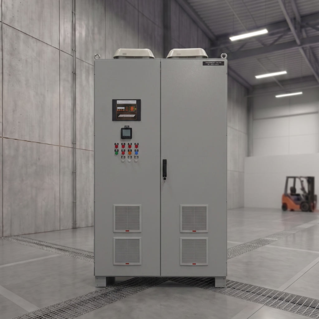
An STS is not a source-selection device in the way an ATS is. It sits downstream, normally after two independent UPS systems, and it exists so that a single-corded load can be fed from a dual-path infrastructure.
The ITIC curve settles the argument
The reason 8 ms and 200 ms sit in different categories is not intuition. It is the ITIC curve (formerly CBEMA), published by the Information Technology Industry Council, which defines the voltage envelope that IT-class equipment is expected to tolerate.
The relevant part: equipment should ride through a complete loss of voltage for up to 20 ms. That figure comes from the hold-up time of the DC bus capacitors in a typical switch-mode power supply.
So:
- An 8 ms STS transfer sits comfortably inside the envelope. The load never notices.
- A 200 ms contactor ATS transfer is ten times outside it. Every SMPS-fed device on that bus drops out.
Which means an ATS placed downstream of a UPS, feeding servers or PLCs, does not protect them. It reboots them.
Two important caveats. First, ITIC describes IT equipment; industrial loads behave differently. Contactor coils typically drop out somewhere between 10 and 30 ms, and a coil that releases takes its motor with it and needs a manual restart or a sequenced recovery in the PLC. Second, hold-up time is specified at full load. A power supply loaded to 90 % may hold up for 12 ms, not 20 — one reason that a “compliant” installation still drops during a real event.
Where each one belongs
ATS, upstream. Utility feed to standby generator. Main incomer selection between two transformers. Anywhere the alternative source needs seconds to become available, and where the downstream UPS provides the ride-through. This is the correct and economical application, and it is what an ATS was designed for.
STS, downstream. In a 2N or Tier III/IV architecture, the infrastructure has A and B paths all the way to the rack. Dual-corded equipment takes both. Single-corded equipment — and there is always single-corded equipment, from network gear to building management controllers to a rack PDU somebody added last year — cannot. The STS bridges that gap: two independent inputs, one output, transfer fast enough that the load stays up.
STS also appears in rail and metro signalling, in power plant auxiliary systems feeding DCS and protection relays, and in any industrial process where an unplanned stop costs more than the switchgear.

What to specify, and what gets forgotten
Source synchronisation window. An STS can only transfer instantly if the two sources are close in phase. Typical acceptance is within 10–20 electrical degrees. Beyond that, the controller must either delay the transfer until phases align — losing the speed advantage — or accept a transient. If A and B derive from separate utility feeds or separate unsynchronised UPS systems, this needs to be resolved at design stage, not commissioning.
Downstream transformer inrush. If there is a transformer between the STS and the load, a transfer at the wrong point in the waveform can drive that transformer into saturation and produce an inrush of several times rated current. Good STS controllers manage transfer timing to limit this. Cheap ones trip.
Fault clearing and selectivity. A downstream short circuit must be cleared by the downstream protective device, not by the STS shutting down and taking the whole bus with it. That requires the STS to sustain a substantial overcurrent for long enough to let a breaker trip — typically 10× rated current for a defined number of cycles — or to transfer onto a maintenance bypass that can supply the fault current. Selective coordination is where the difference between a well-engineered STS and a commodity one becomes visible.
Bypass arrangement. An STS in the power path becomes a single point of failure unless it can be removed from service without dropping the load. Specify a manual maintenance bypass, and confirm it is make-before-break.
Neutral handling. Three-pole or four-pole? Switched neutral or solid? This interacts with the earthing system and with any separately derived source upstream, and getting it wrong produces circulating neutral currents and nuisance earth-fault trips that take weeks to diagnose.
Losses and cooling. SCRs conduct with a forward voltage drop of roughly 1.2–1.5 V per device. On a 1000 A bus that is meaningful continuous heat inside the enclosure. Hybrid designs bypass the thyristors with a contactor after transfer to eliminate the standing loss, at the cost of additional complexity.
Communications. Modbus TCP, SNMP, IEC 61850 for substation environments, plus volt-free contacts. Event logging with millisecond resolution is what lets you reconstruct what actually happened during a disturbance — without it, post-incident analysis is guesswork.
They are not competitors — they are layers
The framing of “STS or ATS” is itself part of the problem. A properly designed critical power path usually contains both, at different levels.
At the top, an ATS selects between the utility incomer and the standby generator. Seconds of transfer time are acceptable there because the layer below absorbs them.
In the middle, two independent UPS systems provide the ride-through and the power conditioning, each fed from its own source path.
At the bottom, a static transfer switch delivers a single output to loads that cannot accept two inputs, transferring fast enough that the load never registers the event.
Removing any layer shifts its job onto a layer that was not designed for it. The most frequent version of this mistake is deleting the STS from a Tier III design to save capital cost, then discovering during a UPS maintenance window that a third of the racks are single-corded and the “redundant” infrastructure has a single point of failure after all.
Critical Power Systems: Reliable UPS, Battery, and Backup Power Solutions
A short decision test
Ask what the load does during a 200 ms loss of voltage.
If the answer is “nothing, the UPS covers it” — an ATS is the correct and cheaper choice.
If the answer is “it reboots”, “the contactors drop out”, “the batch is scrapped”, or “the signalling system fails safe and stops the line” — you need an STS, and you need one specified against the actual fault current, phase relationship and load profile of the installation.
Getting it engineered rather than selected
The parameters that decide whether a static transfer switch performs in a real event — synchronisation window, overload withstand, transformer inrush management, bypass topology, neutral configuration — are exactly the ones that catalogue selection tables leave out.
EPC Energy designs and manufactures static transfer switches and industrial power conversion systems to customer specification, with in-house engineering and full-load Factory Acceptance Testing before shipment. Our STS systems operate in metro and rail infrastructure, data centres, and power plant auxiliary systems, integrated with DCS and SCADA over Modbus, Profinet and IEC 61850.
Send us your single-line diagram and load schedule, and our engineers will return a topology, a bill of materials and a transfer-time analysis against your actual load characteristics.